AHE-250-D02 Service Manual
Introduction
System Overview
The Aqua-Hot 200 Diesel Series is a Hydronic (water-based) Heating Systems that can provide heat and tank-less, continuous hot water in one small, easy to install package.
The Aqua-Hot Heating is a 2-in-1 System
- Interior heating system: provides moist, quiet, comfortable interior heat and even temperatures. It is equipped with one thermostatically-controlled temperature zone.
- Tank-less hot water system: provides a flow of continuous hot water. It produces 90 gallons per hour (1.5 GPM).
The system uses one or a combination of heat sources to heat FDA-approved “Generally Recognized As Safe” (GRAS) propylene glycol based antifreeze solution contained within the Aqua-Hot boiler tank.
The 250-D02 uses a 12-volt DC powered diesel burner as the primary heating source. The diesel burner should be used as the primary heating source for hot water and interior heating needs. The 250 also has one 120-Volt AC 1000-Watt electric element for use (when shore power is available) as a supplemental heating source. Once the tank has been brought to operating temperature by the diesel burner, the electric element can be used to maintain this temperature, as well as provide hot water and interior heat for light-duty applications. The burner and the electric element can be used together or separately.
For continuous hot water or heat in colder conditions, it is recommended to utilize the diesel burner. The electric heating element will provide heat only in mild conditions and provide light duty hot water needs.

Introduction to this Document
Welcome to the Aqua-Hot 250-D02 Service Manual. This manual will serve as a guide for diagnosing and repairing the Aqua-Hot, how to perform standard maintenance, and guide you through troubleshooting procedures to repair the Aqua-Hot. This service manual is designed to aid trained and qualified technicians to properly service and troubleshoot the Aqua-Hot.
Each section in this manual is dedicated to the diagnosis of specific components within the Aqua-Hot which may be inhibiting the operation of the heater.

Read all instructions before servicing the Aqua-Hot unit. AquaHot Heating Systems is not liable for damage resulting from failing to follow instructions contained in this, and any other Aqua-Hot documentation relevant to this unit.
- Read this manual before servicing or using the Aqua-Hot System to reduce the risk of injury to persons or damage to the equipment.
- The product identity label contains specifications of the unit, to what standards it has been tested, and important safety notices.
- The Aqua-Hot must be installed in a compartment that is closed off from living quarters and accessible only from the exterior of the vehicle.
- Propylene glycol based antifreeze “Generally Recognized As Safe” (GRAS) by the FDA must be utilized for the antifreeze and water heating solution.
- An interlock switch prevents the Aqua-Hot heater from operating when the cover is not installed in the correct position.
- Disconnect electric wiring to the Aqua-Hot System before welding or plasma cutting the RV to avoid damage to equipment.
- The Aqua-Hot tank and heating loop operate at 0.0 PSI (zero pressure system). Air pressure to the tank must not exceed 20 PSI. Exceeding this rating will cause internal damage to the Aqua-Hot.
- Use caution when working on or near any diesel fuel system.
- Do not store or use gasoline or other flammable vapors or liquids in the vicinity of this or any other appliance.
- The Aqua-Hot’s exhaust is HOT and must be kept away from heat sensitive material.
- DO NOT connect the 12-volt DC power to the Aqua-Hot if the vehicle requires welding.
- At maximum operating temperature, the coolant will be very hot and scalding. Hot vapor or coolant may cause in serious burns or injury. Be aware of hot surfaces.
- Do NOT activate the burner until the antifreeze and water heating solution has been added to the boiler tank to avoid serious damage to the heater.
- Installation and repairs may only be carried out by an authorized, factory-trained Aqua-Hot technician. The heating system must be installed in accordance with local codes, or in accordance with the Standard for Recreational Vehicles, (RVIA) ANSI A 119.2/NFPA 501C, NFPA 1192.

WHAT TO DO IF YOU SMELL GAS
- Evacuate all persons from the vehicle.
- Shut off the gas supply as the gas container or source.
- Do not touch any electrical switch or use any phone or radio in the vehicle.
- Do not start the engine or electric generator (if equipped).
- Contact the nearest gas supplier or qualified service technician for repairs.
- If you cannot contact the nearest gas supplier or qualified service technician, contact the nearest fire department.
- Do not turn on the gas supply until the gas leak or leaks (if relevant) have been repaired.
- Installation and service must be performed by a qualified installer, service agency, or gas supplier.
The Aqua-Hot’s exhaust is HOT!
- Do NOT park in areas where dry conditions exist (IE grassy, dry fields).
- Do NOT operate the burner inside an enclosed building.
- The heater must be switched OFF when refueling.

Maintenance Schedule
Monthly Maintenance
Check the Aqua-Hot’s antifreeze and distilled water heating solution to ensure that it is at the proper level. This can be accomplished by visually checking the coolant level in the Aqua-Hot’s expansion bottle; reference Figure 26 on page 20. Please note that the coolant level should be checked ONLY when the Aqua-Hot is at maximum operating temperature. This should be done immediately after the electric element disengages, or after the diesel burner has completed a cycle. At maximum operating temperature, the antifreeze and distilled water heating solution should be at the level marked “HOT” on the expansion bottle.
| Note: It is also recommended to run the diesel burner at least once a month for a full cycle (at least 20 minutes) to ensure optimum heater condition. |
Annual Maintenance
To maintain the Aqua-Hot at its full potential, it is highly recommended to have the diesel burner tuned up annually. This involves the fuel nozzle and fuel filter replaced, burner cleaned, inspecting the exhaust and combustion air lines for damage and ensure they are clear, checking the fuel lines for any leaks, checking the hoses and wiring to make sure there is no damage or cracks. See Page 79 for more in-depth information.
Replenishing the Heating Solution
If the antifreeze and distilled water heating solution needs replenishing, remove the cap for the expansion bottle and fill it to the “HOT” mark (only when the tank is to temperature). Replace the expansion bottle cap when this is complete. DO NOT operate the unit without first replacing the cap of the bottle. Reference Figure 26 for additional information. Excess air will escape through this bottle as the stir pump of the unit operates. While bleeding this system of air, it will be necessary to continue to fill the bottle until this process is complete. The Aqua-Hot does not need regular replacement of the propylene glycol antifreeze and water heating solution, but if more antifreeze is required, contact Aqua-Hot Heating Systems to purchase antifreeze, or for guidance in selecting an appropriate antifreeze product for use with this unit.


In order to provide the best freeze protection, boil-over protection, anti-corrosion, and rust protection, a mixture of 50/50 propylene glycol antifreeze and distilled water is recommended. The Aqua-Hot 250-D03 boiler tank holds approximately 3.7 gallons.
The mixture may be modified to provide the most adequate freezing, boiling, and rust/anti-corrosive protection. A 50/50 mixture of propylene glycol and distilled water has a freeze point of approximately -35°F and a boiling point of approximately 223°F. Refer to the table below to determine the best protection mixture ratio and also reference page 55 for the proper tool and instructions for use in measuring the system’s antifreeze mixture ratio.
Overheat Protection
Every Aqua-Hot is equipped with at least two overheat protection devices. These are commonly known as the highlimit thermostats. These thermostats operate by maintaining a circuit while the unit is below 218°F.
In the event of an overheat condition, the high limit thermostats will cut the operating signal to the gas burner, and/or the electric element. When this signal is interrupted, the electric element and gas burner will immediately disengage. Contact Aqua-Hot Heating Systems LLC for assistance in locating a qualified person to service this heater after an overheat situation.

System Features

System Specifications
Electric Element
Power Consumption ......................................1000 W (maximum)
Voltage ..............................................................................120V AC
DC Power
Heat Input ..................................................56,000 BTU/hr ± 10%
Fuel Consumption ..................................................0.40 gallon/hr
Power Consumption .........................................108W (maximum)
Zone Heat
Circulation Pumps ...........................................................................................1
Power Consumption (max) ..................................................... 21W
Voltage ............................................................................... 12V DC
Heating Zones
Maximum ......................................................................................1
Domestic Water Heating
Maximum ......................................................................... 1.5 GPM
Physical Specifications
Dimensions (US)...................................26”L x 12.46”W x 17.2”H
Dry Weight ........................................................................... 84lbs.
Wet Weight ......................................................................... 104lbs.
Component Cut-Away

| Component Chart | |||
| 1. Access Cover Screw | 6. Diesel Burner Assembly | 11. Diesel Fuel Return Port | 16. Boiler Tank |
| 2. Drain Valve | 7. Interlock Switch | 12. Diesel Fuel Supply Port | 17. Domestic Hot-Water Coil |
| 3. 3-Way Valve | 8. Domestic Cold Water Inlet | 13. Expansion Tank Connection | 18. Relay Control Board |
| 4. Diesel Burner Controller | 9. Domestic Hot Water Outlet | 14. Heating Zone Return Port | 19. Zone Circulation Pump |
| 5. Tempering Valve | 10. 120V AC Connection | 15. Heating Zone Outlet Port | |
Operational Flow Chart

Relay Control Board
The relay control board at use in your Aqua-Hot 250 Diesel Series is designed to function in conjunction with the Diesel Burner Controller to allow the heater to operate. This section will introduce you to the basic functions of the board.
Indicator lights line the bottom of the relay control board and are designated D1 through D6. Each of these lights indicates a function or event that is taking place. The detailed function of these lights will be explained on the next page.
- D1: Heating Status Light (orange)
- D2: Electric Element Power (green)
- D3: Pump Power (blue)
- D4: Low-Temperature Cutoff Status (yellow)
- D5: Burner Status (green)
- D6: Interior Zone Heating (orange)
Fuse Functions, Locations, and Ratings:
There are three fast-blow fuses included with this relay board and may need to be replaced if they cease to function. The cradles for these fuses are labeled FH1, FH2, and FH3 and will contain either a 5A or 10A fuse. The 250-D02 does not utilize the 5A fuse in slot FH3, it uses a 20A fuse integrated into the wiring harness to fill this need.
- FH1: 10A - AC Activation Circuit and Burner
- FH2: 5A - Switch Power
Note on Diagnosing the Relay Control Board:
If after diagnosing the Aqua-Hot you believe that the relay control board is at fault, it is very strongly advised that you contact Aqua-Hot Heating Systems Technical Support to ensure that the issue has been accurately diagnosed. These components have a very low rate of failure, and for that reason, we recommend contacting us before replacing it in an attempt to reduce down time and unit repair costs.

Heating Status (D1):
This indicator light will illuminate orange when the burner and/or electric element switch on the interior switch panel is ON and the control thermostat is calling for heat. If the heater is functioning and the light is not illuminated, or the heater is not functioning and the light is illuminated, there is an issue with the wiring or one of the components.
Electric Heating Element Status (D2):
This indicator light shows the status of the electric heating element by illuminating green when the electric element switch is ON. If the green LED does not illuminate, the electric element switch is OFF or the unit is low on fluid. The D2 light functions with the interior electric element switch to provide functionality when requested. When the electric element switch is ON, the D2 light should also be on. If the D2 indicator light is not illuminated, but the electric switch on the interior switch panel is in the ON position, there is a short in the 12V DC side of the electric element circuit. This could be due to a bad connection, a bad switch, a bad fluid level sensor, or the fuse present in FH2 is not functional.
| Note: It is possible for the Electric Heating Element and Heating Status lights to be illuminated, and the electric element not function due to an issue with the 110V AC power supply. |
Circulation Pump (D3):
This indicator light shows the power status of the circulation pump within the Aqua-Hot. The circulation pump is responsible for circulating fluid through the heating zone, and stirring the fluid within the tank while it is heating.
The system functions correctly if the coach thermostat is calling for heat, the pump is operating, ad the light is illuminated blue. If the light is off while the coach thermostat is calling for heat or hot water, there may be an issue with the coach wiring or with the relay control board.
Low-Temperature Cutoff Status (D4):
The low-temp cutoff status thermostat deactivates interior heat when domestic hot water is being used, and activates the stir pump in conjunction with the burner switch. When this light is on, it indicates that there is either a demand for hot water, or the Aqua-Hot is not yet up to operating temperature.
Burner Status (D5):
This indicator light shows the status of the burner by illuminating green when the burner switch is on. On the 250- D02 model, the indicator light on the switch panel will not illuminate if the burner is faulting.
If the burner switch is in the ON position and the control thermostat is calling for heat, the D5 indicator light should illuminate in addition to the D1 heating status light.
If the indicator light remains off while the burner switch is in the ON position, it could indicate that there is a short present, the fuse in FH2 may be burned out, or the unit may be low on fluid.
Heating Zone Status (D6):
This light indicates that status of the coach thermostat and the heat exchanger fans. The indicator light will illuminate orange when the coach thermostat is requesting interior heat, or hot water is being requested.
If a fault condition occurs, it could be due to a wiring issue, a faulty thermostat, or issues with the heat exchanger fans.
Interior Switch Panel Introduction:
The interior switch panel is used to control the two potential heating sources for the Aqua-Hot’s boiler tank. When a switch is activated, the indicator light on the switch will illuminate. Burner Switch: When the burner switch is in the ON position, the control thermostat will communicate with the relay control board and the burner controller that heat is needed for the tank. The burner will activate and the unit will begin to warm up.
A cold boiler tank can be expected to reach temperature in approximately 10-20 minutes, depending on the ambient temperature. In colder temperatures, it may take longer to heat the unit to its operating temperature.
In order to reach and maintain temperature under all demands, the burner switch must be in the ON position. Keep in mind that the electric element is a supplemental-only heat source. This means that the element can provide hot water for simple tasks such as hand-washing, and maintaining tank temperature at times when there is no load. The burner is intended as the primary heat source.
Additionally, the burner switch can be used to reset a lowvoltage condition. This is accomplished by turning the switch OFF for 30 seconds, and then turning it back on. This is known as “power-cycling”.
Electric Element Switch:
When the coach is plugged into an AC power source (i.e. shore power or a generator) and the electric element switch is ON, the electric heating element will be used to provide heat to the boiler tank if the need arises. A cold boiler tank can expect to be brought to operating temperature by the electric heating element in 1-2 hours depending on the ambient temperature. The electric element is intended as a secondary, supplementary heating source. If used alone, the electric element will NOT be able to provide enough heat for continuous hot water or interior heat.


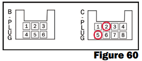
| Note: The Burner and Electric Element switches must possess a jumper wire between Pin 4 and Pin 10 as depicted. |


| Receptacle Housing Information | ||
| Manufacturer | Mating Part No | Description |
| TE Connectivity | 1-480709-0 | Mate-N-Lock |
| Switch Panel Wiring | |
| AC Electric Switch | AC Control Switch Plug |
| Pin 4 | Pin 9 |
| Pin 2 | Pin 10 |
| Pin 9 | Chassis Ground |
| Burner Switch | 8-Pin Harness Plug |
| Pin 4 | Pin 4 |
| Pin 2 | Pin 5 |
| Pin 9 | Chassis Ground |
| Pin 10 | Pin 11 |
| Pin-Out Information | ||
| Pin | Wire | 8-Pin Harness Connection |
| Pin 1 | #3 | Vehicle Battery (+) |
| Pin 2 | #2 | Vehicle Battery (-) |
| Pin 3 | #11 | Burner ON signal |
| Pin 4 | #10 | Burner Switch Power |
| Pin 5 | #14C | Thermostat Power Output |
| Pin 6 | #19 | Thermostat Power Input |
| Pin 7 | #18 | Heat Exchanger Fans (+) |
| Pin 8 | #1 | Heat Exchanger Fans (-) |
| Pin 9 | #26 | Electric ON Signal |
| Pin 10 | #15 | Electric Switch Power |
| Pin 11 | #30 | Burner Indicator Light |
| Pin 12 | #17 |
Optional Boost Pump (not relevant on all coaches) |
Exhaust System Requirements
Introduction:
The Aqua-Hot’s exhaust is hot and must be kept away from any heat-sensitive material. Therefore, the exhaust system should be checked to ensure that it continues to meet the following requirements.
- The exhaust must not be directed downward as a fire could result when parked in dry, grassy areas.
- The exhaust must not terminate underneath the vehicle, underneath an openable window or vent, in the awning area of the coach (if applicable), or near the slide-out areas.
- The exhaust must be able to freely exit away from the vehicle without any obstructions.
- Use standard two-inch automotive-type exhaust piping and avoid bends if possible.
- The 3-inch and 4-inch black pipe nipple and the exhaust elbow, originally supplied with the Aqua-Hot must be used (kit sold separately).
- Mounting must be place every three feet to adequately support the exhaust system.
- Total exhaust system length must not exceed 30ft in total length, and shall contain no more than two 90° bends.

Components
Introduction:
This section of the Service Manual details various components of the Aqua-Hot that may require troubleshooting and/or replacement in the event of malfunction. Replacement parts can be ordered online through AquaHot’s webstore at www.aquahot.com.
If additional assistance is needed, the technical support team can be contacted at 574-AIR-XCEL (574-247-9235) Monday through Friday, 7am to 4pm Mountain Standard Time.
| Note: Before attempting to troubleshoot any Aqua-Hot component, please check all wiring to ensure that there is no corrosion, loose and/or faulty wiring connection present which may be causing failure. |
Interlock Switch
The interlock switch is a safety device designed to ensure that the Aqua-Hot’s access cover is securely installed before the burner will operate. Troubleshoot the interlock switch if the following conditions occur:
- The burner fails to operate
- The burner indicator light does not illuminate when the switch is in the ON position
Troubleshooting:
- Ensure that the boiler tank has sufficiently cooled in order to require heat from the burner.
- Activate the burner switch located on the interior switch panel.
- Locate wires #11B and #24 on the wiring harness as they lead into the interlock switch.
- Disconnect the wires from the switch, noting that wire #24 is connected to the terminal labeled “NO” and #11B is connected to the terminal labeled “COM”.
- Using an ohmmeter, check the interlock switch for continuity while the switch button is manually depressed.
- If continuity is not present with the button pressed in, follow the instructions in this section to replace the interlock switch.

Replacement Procedure
- Disconnect the interlock switch wires by pulling the quick connectors from the switch spade terminals.
- Release the interlock switch from the Aqua-Hot cabinet by pushing in on the locking tabs and pulling the interlock switch.
- Remove the defective interlock switch from the AquaHot.
- Install the replacement interlock switch into the AquaHot ensuring that the locking tabs snap into place.
- Connect the Aqua-Hot’s replacement wires to the replacement interlock switch with wire #24 connected to the terminal labeled “NO” and wire #11B connected to the terminal labeled “COM”.


Fluid Level Sensor
Introduction:
The fluid level sensor monitors the current fluid level within the Aqua-Hot. This device is intended as a fail-safe measure which will disengage the Aqua-Hot if the fluid ever drops below a set threshold. The fluid level sensor is located on the expansion bottle, which is mounted to the side of the unit (see below).

If the fluid level sensor is malfunctioning, the Aqua-Hot will show no signs of operation whatsoever. Troubleshoot this sensor if there is an adequate amount of fluid present within the Aqua-Hot, and the unit does not operate:
- The burner fails to operate
- The burner switch indicator light fails to illuminate
- The electric element fails to operate
- The indicator light on the electric switch does not illuminate

Troubleshooting Guidelines:
Before troubleshooting the fluid level sensor, ensure that the following requirements have been met.
- The fluid expansion bottle is filled to at least the “COLD” mark.
- Verify that all coach-side in-line fuses are functional.
- Ensure that the unit is completely cool.
- Ensure that DC electrical power is supplied to the Aqua-Hot.
- Ensure that AC electrical power is supplied to the AquaHot’s electric element.
- Ensure that the fluid level sensor is oriented correctly (see below).

If any of the requirements above are not fulfilled, correct them before continuing to diagnose the fluid level sensor. Reference the troubleshooting guide below.
Troubleshooting Procedure:
- Verify that the Aqua-Hot’s expansion bottle is full of antifreeze and water heating solution.
- Verify that the wiring is secure, and in good working condition.
- Locate the wiring harness for the unit. Find wires #10, #15, and #16. Wires #10 and #15 will co-terminate in a yellow connector.
- Disconnect these wires from th expansion bottle, and test for continuity across the expansion bottle sensor.
- If the bottle contains fluid and continuity does not exist across the fluid level sensor, the sensor will need to be replaced.

Replacement Procedure:
In order to replace the fluid level sensor, the overflow bottle must also be replaced. Please visit www.aquahot.com or call 574-AIR-XCEL (574-247-9235) to order the expansion bottle kit. Once you have the replacement part in hand, follow the procedure below.
- Locate the fluid expansion bottle.
- Clamp the overflow hose as close to the bottom fitting as possible.
- Grab a bucket or drain receptacle and place it directly under the lower fitting of the expansion bottle.
- Remove the clamp from the lower fitting of the expansion bottle.
- Remove the hose and allow the excess fluid to drain into the bucket.
- Remove the overflow hose from the upper fitting of the expansion bottle.
- Remove the old expansion bottle, disconnect the Faston connectors, and discard the old bottle.
- Secure the new bottle in position.
- Crimp the new faston connectors to the new fluid level sensor.
- Connect these wires to their receptacles on the Aqua-Hot harness.
- Reconnect the overflow hose to the upper fitting.
- Reconnect the expansion hose to the lower fitting.
- Fill the bottle with the previously drained fluid.
- Remove the hose clamps.
- Test the Aqua-Hot for normal functionality.


Control Thermostat
The control thermostat is installed into the Aqua-Hot’s boiler tank and monitors the temperature of the antifreeze and water heating solution to determine when it is at operating temperature and when it requires heat. The Aqua-Hot is considered to be at operating temperature between 155°F and 188°F. Please reference Page 10 for the relay control board LED indicator information.

Troubleshooting Conditions:
Troubleshoot the control thermostat if one of the following conditions has occurred:
- There is a lack of hot domestic water and/or interior heat.
- The orange heating status light (D1) does not illuminate while the unit is below 175°F.
Troubleshooting:
- Verify the following before troubleshooting the control thermostat:
- The Interlock Switch is depressed (access cover is properly installed).
- The overflow bottle is adequately filled.
- The High-Limit Thermostats are not tripped.
- Fuses in the relay control board are functional.
- Turn the burner and/or electric element switch to the ON position.
- Check the relay control board to ensure that “Electric Heating Element Status” (D2) and/or “Burner Status” (D5) indicator light is illuminated.
- Verify that the “Heating Status” (D1) indicator light on the relay control board is illuminated as it should be whenever the Aqua-Hot is below 175°F.
If the “Heating Status” (D1) indicator light is not illuminated, check the following:
- Verify that the temperature of the boiler tank has fallen below the 175°F minimum operating temperature by checking with an infrared thermometer. Take the reading within 12 inches from the painted tank surface with the thermometer set to “High Emissivity” or similar. Do not attempt to take readings on a shiny surface.
- If below 175°F, disconnect the control thermostat’s wires from their connection. Using an ohmmeter, check for continuity across the control thermostat.
If continuity does not exist across the control thermostat under these conditions, follow the directions in this section for replacing the control thermostat. If continuity exists across this thermostat, inspect it, and the wiring harness for any damage.

Control Thermostat Replacement Procedure
- Ensure that the Aqua-Hot has been completely shut down, all power sources disconnected, and the unit has been allowed to cool completely.
- Clamp the hoses indicated below with pinch off pliers to prevent drainage of the heating zone loop.
- Drain one gallon of antifreeze and water heating solution into an external contained to be reused later.
- Disconnect the defective control thermostat wires by separating the quick disconnect terminals.
- Using a ⅞” deep wall socket, unscrew the control thermostat from the Aqua-Hot’s boiler tank.
- Wrap the threads of the replacement control thermostat with 6 wraps of thread seal tape.
- Reconnect wire #14A and wire #23 to the new control thermostat.
- Refill the Aqua-Hot’s boiler tank with the previously drained antifreeze and water heating solution.
- Refill the Aqua-Hot using an external fill pump, filling through the zone fill.
- Test the Aqua-Hot for normal operation.
- Test the interior heating loop to ensure that there are no air pockets trapped within the interior heating loop.
- If necessary, purge the interior heating loop according to the guide on Page 85.


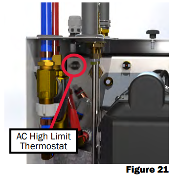
AC High-Limit Thermostat
Introduction:
The AC high-limit thermostat serves as a safety measure in the event that the electric heating element continues to operate after the maximum operating temperature has been reached. The high-limit thermostat allows the current for the heating element to pass through until the boiler tank reaches a temperature of 215°F. Should this temperature be reached, the high-limit thermostat blocks the current to the element, preventing the element to continue to operate.
| Note: If the high-limit thermostat is tripped, it is recommended to test the control thermostat and AC relay for proper operation. |
Begin troubleshooting the AC High-Limit Thermostat if the electric element fails to operate correctly.
Troubleshooting Guidelines:
The following conditions must be met before the AC High-Limit Thermostat can be diagnosed, and if necessary, repaired.
- The fluid expansion bottle is filled to at least the “COLD” mark.
- Verify that all in-line fuses are functional. • Ensure that the unit is completely cool.
- Ensure that DC electrical power is supplied to the Aqua-Hot.
- Ensure that AC electrical power is supplied to the Aqua-Hot’s electric element.
If any of the above conditions are not met, correct them before continuing with troubleshooting. Results of the troubleshooting procedure cannot be verified if the conditions listed above are not fulfilled.

Troubleshooting Procedure:
- Verify the following before troubleshooting the AC high-limit thermostat:
- The control thermostat is calling for heat.
- The interlock switch is depressed.
- The overflow bottle is adequately filled.
- The high-limit thermostats are not tripped.
- The fuses in the relay control board are functional.
- Ensure that the unit has been shut down and completely cooled before continuing.
- Shut off the coach-side power breaker to the Aqua-Hot.
- Disconnect the 3-pin AC Molex plug from the AC relay enclosure. Leave the DC power supply connected.
- Activate the “ELECTRIC” switch on the switch panel inside the coach.
- Using a multimeter, test for continuity across the AC highlimit thermostat by placing one lead on the unit-side Molex connection as shown below.

- If no continuity exists, locate the AC high-limit thermostat and depress the center button to reset it. Retest for continuity.

- Move the electric switch to the OFF position. Reset for continuity. If continuity still exists, replace the AC relay.
Replacement Procedure:
If it has been determined that the high-limit thermostat needs to be replaced, it can be easily replaced by following the directions below.
- Shut off gas, electric, and water supply to the Aqua-Hot.
- Disconnect the domestic water inlet and outlet line fittings from the Aqua-Hot.
- Unscrew the nut that affixes the mixing valve to the left side of the Aqua-Hot cabinet wall.

- Push down on the mixing valve to expose access to the AC high-limit thermostat.
- Cut the wire tie which wraps the wires on the left side of the unit.
- Cut the black wires on the AC high-limit thermostat as close as possible to the body of the thermostat and strip the other end.
- Remove the faulty high-limit thermostat using a ⅝” socket or crow’s foot.
- Butt-splice a new AC high-limit thermostat to the stripped wire.
- Reinstall the AC high-limit thermostat using a ⅝” socket or crow’s foot.
- Re-secure the wires using the extra wire tie provided and reinstall the mixing valve assembly.
- Make sure the replacement AC high-limit thermostat is functioning properly by testing for continuity across this thermostat.
- Reposition the tempering valve assembly onto its mounting stud on the left cabinet wall.
- Re-secure the tempering valve assembly with the previously removed nut.
- Reconnect the domestic water connections to the PEX fittings of the tempering valve assembly.
- Reestablish the gas, electric, and water supply to the AquaHot.
- Test for unit for normal operation.

Burner High-Limit Thermostats
Introduction:
The burner high-limit thermostats serve as a safety measure in the event that the burner continues to operate after the maximum operating temperature (215°F) has been reached.
If the system reaches an over-temperature condition by interrupting the fuel solenoid, preventing diesel fuel from entering the combustion chamber.
Begin troubleshooting the High-Limit Thermostats if the following conditions have occurred:
- The fuel solenoid fails to operate.
| Note: If the high-limit thermostat continues to trip, troubleshoot the control thermostat and verify that the boiler tank is full of antifreeze and water heating solution. |
Troubleshooting Guidelines:
The following conditions must be met before the AC HighLimit Thermostat can be diagnosed, and if necessary, repaired.
- The fluid expansion bottle is filled to at least the “COLD” mark.
- Verify that all in-line fuses are functional.
- Ensure that the unit is completely cool.
- Ensure that DC electrical power is supplied to the Aqua-Hot.
- Ensure that AC electrical power is supplied to the AquaHot’s electric element.
If any of the above conditions are not met, correct them before continuing with troubleshooting. Results of the troubleshooting procedure cannot be verified if the conditions listed above are not fulfilled.

Troubleshooting Procedure:
- Locate the high-limit thermostats (see Figure 24).
- Disconnect the burner thermostats using the information below:
- Jumper wire and wire #32 (left) or wires #33 and jumper wire (right)
- Place a jumper wire between the two wires on the harness to bypass the high-limit thermostat. Check the Aqua-Hot for normal operation.
- Disconnect the DC high-limit thermostat wires, then, using an ohmmeter, check the thermostat for continuity.
- If continuity does not exist, depress the button in the center of the thermostat to reset. Reset for continuity.
- If the thermostat at this point still does not have continuity, follow the instructions in this section to replace the thermostat.
Replacement Procedure:
- Ensure that the Aqua-Hot has been completely shut down, all power sources disconnected, and the unit is allowed to cool completely before continuing.
- Remove the two wires from the defective high-limit thermostat.
- Using a ⅝” socket or crow’s foot, remove the defective high-limit thermostat from the face of the tank.
- Install the replacement high-limit thermostat into the port on the face of the boiler tank and finger-tighten into place.
- Reconnect Jumper wire and wire #32 (left) and/or wires #33 and jumper wire (right) to the high-limit thermostat which has just been replaced.
- Test for normal operation.

Low-Temperature Cutoff Thermostat
Introduction:
The Low-Temperature Cutoff Thermostat (LTCO) operates the domestic hot water priority system by blocking the interior heating feature when domestic hot water is being used. This ensures that even heat is provided for domestic hot water, which avoids the possibility of cold water pockets during showers and other heavy-load applications. Ensure the Aqua-Hot is up to temperature before troubleshooting the Low-Temperature Cutoff Thermostat.

Troubleshooting Condition:
This thermostat should be diagnosed if there is a lack of interior heat or hot water, the D4 light is not illuminated, and the tank is up to operating temperature.
Troubleshooting Procedure:
Use the following troubleshooting tree to diagnose the LowTemperature Cutoff Thermostat.
- Verify the following before troubleshooting the lowtemperature cutoff thermostat.
- The control thermostat is calling for heat
- The interlock switch is depressed
- The overflow bottle is adequately filled
- The high-limit thermostats are not tripped
- The fuses on the relay board are functional
- Determine if the unit is ready to provide heat by verifying that the “Low-Temperature Cutoff Status” light is NOT illuminated on the relay control board.
- Verify that the Aqua-Hot is at operating temperature between 155°F and 185°F by using a meat thermometer secured to the tank face.
- Verify that domestic hot water is not being used.
- If the ‘Low-Temperature Cutoff Status” light on the relay control board is illuminated after the unit has reached operating temperature, complete the following:
- Disconnect wire #14B and #25 from the lowtemperature cutoff thermostat.
- If the light does not go out after disconnecting the low-temperature cutoff thermostat, contact Aqua-Hot Heating Systems for assistance in diagnosing this issue.
Lack of Hot Water
- If the LTCO indicator light does not illuminate when domestic water is being used or when the Aqua-Hot falls below operating temperature, complete the following:
- Using a temperature sensor, verify that the LTCO thermostat is below 90°F.
- Inspect the wiring to ensure that the Aqua-Hot is wired properly and that the LTCO thermostat has not been disconnected.
- Disconnect both wires from the Low-Temperature Cutoff Thermostat. Using a jumper wire, connect these two wires together.
- With the jumper wire installed, check the coach for hot water availability. If after jumping these wires together and hot water has been established, the Low-Temperature Cutoff Thermostat will need to be replaced.
Replacing the Low-Temperature Cutoff Thermostat:
- Ensure that the Aqua-Hot has been completely shut down and that all the power sources have been disconnected.
- Locate the Low-Temperature Cutoff Thermostat on the Aqua-Hot.
- Disconnect the defective LTCO thermostat by separating the quick-disconnect terminals.
- Using a ⅝” wrench or crow’s foot wrench, remove the defective LTCO thermostat from the Aqua-Hot.
- Install the replacement LTCO torquing it to 15 in-lbs ONLY. Anything more than 15 in-lbs of torque will damage the thermostat and possibly the unit.
- Connect wire #14B and wire #25 to the replacement LowTemperature Cutoff Thermostat.
- Test for normal operation.


Three-Way Valve
Introduction:
The Aqua-Hot has a three-way directional valve to control coolant priority within the unit. This ensures that there will be a supply when heated water is being called for, but can provide interior heating when the need arises.

Troubleshooting Condition:
Troubleshoot the three-way valve if the following conditions have occurred:
- An absence of interior heat
- Inconsistent or complete lack of hot water
Troubleshooting:
- Verify the following before troubleshooting the three-way valve:
- The control thermostat is calling for heat
- The interlock switch is depressed
- The overflow bottle is adequately filled
- The high-limit thermostats are not tripped
- The fuses on the relay board are functional
- Verify that the heating zone is operating properly by checking the hoses to see if they are hot to the touch when a heating zone is calling for heat.
- Locate the relay control board and ensure that both the heating zone status (D6) and the pump status (D3) indicator lights are illuminated.
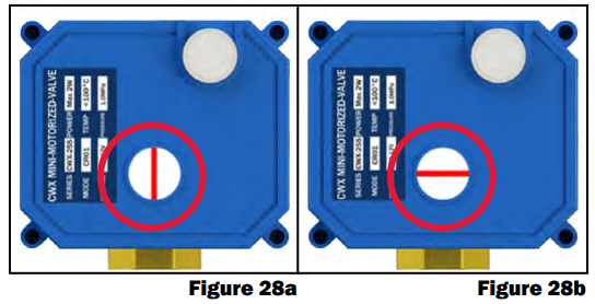
- Verify that the line on the valve display window is vertical when interior heat is being called for. If this is not occurring, check the LTCO thermostat for functionality (reference Page 22).
- Verify that the line on the valve display window is horizontal when hot water is being requested. This is known as “stir” mode.
- Ensure that the modes change between interior heat (vertical) and hot water (horizontal), and verify that it matches the relay control board lights. D6 should illuminate while the sight glass is vertical.
- Locate the wires traveling from the three-way valve as listed below:
- The wires of the three-way valve will terminate at the 16-pin plug of the relay control board.
| Note: The following tests (step 6 & 7) will verify functionality of the internal workings of the three-way valve with power directly applied. The valve should actuate, and the sight glass should rotate with at least one of the following tests. |
- Apply 12V DC power to the red wire, and attach a ground wire to the green/black wire. The motor within the threeway valve should activate, rotating the red line in the sight glass vertically (Figure 28a).
- Apply 12V DC power to the green/black wire, and attach a ground wire to the red wire. The motor within the threeway valve should activate, rotating the red line in the sight glass horizontally into “stir” mode (Figure 28b).
- If the three-way valve does not function in either of the above tests, it will need to be replaced. Follow the instructions on the next page to replace this component.

Replacement Procedure:
- Ensure that the Aqua-Hot has been completely shut down, all power sources have been disconnected, and the unit has completely cooled.
- Use clamp hose pliers to pinch tubing surrounding the three-way valve as indicated in Figure 30.
- Remove the valve wires from the green connector plugged into the relay control board.
- Using constant tension pliers, loosen and slide back the constant tension clamps securing the hose to the defective valve.
- Remove the hose from the defective valve as shown in Figure 31.
- Remove the two remaining hoses from the defective threeway valve.
- Slide the hoses onto the valve and set the constant tension clamps back into place.
- Install the replacement three-way valve according to the specific instructions below related to your unit.
- Reconnect the red wire to Pin #7, and the green wire to Pin #8 of the relay control board connector.
- Crimp a female 22-18AWG “Faston” connector to the green/black wire of the three-way valve. Connect to wire #22 “Faston” connector.

- Refill the Aqua-Hot’s boiler tank, purging the heating loop if necessary.

Tempering Valve
Introduction:
The tempering valve of the Aqua-Hot mixes the heated domestic water from the boiler tank with cold incoming domestic water at a preset ratio to deliver steady hot water and reduce the risk of scalding. It is recommended that you review the “Lack of Hot Water Troubleshooting Guide” prior to diagnosing the tempering valve.
Troubleshooting Condition:
Troubleshoot the tempering valve if the following conditions have occurred:
- A lack of hot water.
- Hot water supply is uneven.
- Hot water is too hot.
- The D4 light is not illuminated.
Troubleshooting Condition:
- Inspect the tempering valve to ensure that it is not leaking.
- Activate the burner and allow the unit to heat unit the burner shuts off. This test cannot to be accomplished with the electric element.
- Open the hot water valve on an interior faucet without a hot-stop and allow the temperature to stabilize at its hottest point.
- Using a meat thermometer, take temperature reading of the water. It should be between 115°F and 120°F. Be aware that a water source temperature of less than 65°F may prevent hot water from reaching this threshold.
- Test the tempering valve’s functionality by turning the knob (see Figure 32). If the knob does not rotate, this tempering valve will need to be replaced. On newer heaters, it will be necessary to remove a black plastic cap from the body of the tempering valve.
- While running water, if the inlet pipe is excessively hot while the outlet is lukewarm and adjusting the mixing valve results in no change, it may be a faulty mixing valve.
- If adjustment of the mixing valve is able to effect change in temperature, it must be continually adjusted until the output range of the hot water is between 115°F and 120°F.
| Note: Adjusting the mixing valve beyond 120°F will result in a lack of hot water and may result in scalding. Do NOT attempt to adjust the tempering valve without assistance from Aqua-Hot Technical Support or a qualified Aqua-Hot technician. |

Replacement Procedure:
- Turn off the coach water supply.
- Drain the water pressure by opening the faucets and allowing the water to drain.
- Disconnect the coach water lines from the tempering valve assembly.
- Disconnect the PEX pipe fittings from the tempering valve assembly.
- Remove the pressure relief valve assembly from the tempering valve assembly.
- Using a back-up wrench, unscrew the tempering valve from the Aqua-Hot. Failure to use a back-up wrench could result in damage to the cold water inlet pipe.
- Remove the brass fittings from the defective tempering valve.
- Install the brass fitting onto the replacement tempering valve. Use thread seal on the fittings.
- Install the replacement tempering valve onto the AquaHot using the back-up wrench to tighten.
- Install the pressure relief valve onto the replacement tempering valve. Use thread seal tape.
- Reconnect the PEX pipe and fittings onto the replacement tempering valve. Use thread seal tape. Be sure to inspect rubber seals and replace is necessary.
- Reconnect the water lines to the tempering valve.

Circulation and Stir Pump
Introduction:
The fluid circulation pump operates to provide fluid circulation to either the interior heating zone or the antifreeze boiler tank depending on the heating and hot water needs at the time. It is used when interior heat is demanded by circulating propylene-glycol and water through the heating loop. It is used to stir the fluid mixture in the tank to ensure optimal hot water performance. The pump will also circulate the tank fluid while the burner cycles on to ensure that the tank is completely and evenly heated during a normal operating cycle.

Troubleshooting Condition:
Troubleshoot the circulation pump if the following conditions have occurred:
- A lack of interior heat.
- Lack of hot water or supply is uneven.
Troubleshooting Procedure:
Follow the procedure to diagnose the fluid circulation pump.
- Verify the following before troubleshooting the circulation and stir pump:
- Activate an interior zone for heating and the burner switch. Locate light D6 on the relay control board.
- Light D6 should illuminate and the circulation pump should begin operating.
- If the circulation pump still does not operate, locate wire #20 on the wire harness, and apply 12V DC current directly to the pump.
- If the pump operates with 12V DC applied, begin diagnosing the relay control board.
- If the pump does not operate with 12V DC directly applied to it, the pump will need to be replaced.

Replacement Procedure:
- Ensure that the Aqua-Hot has been completely shut down, all power sources have been disconnected, and that the unit has been allowed to cool completely.
- Clamp the zone outlet, and the zone return with hose pinchpliers as shown below.
- Drain the antifreeze and water heating solution from the Aqua-Hot’s boiler tank using the drain valve.
- Disconnect the defective pump’s wires by removing the electrical plug from the pump body.
- Using constant tension pliers, loosen and slide back the constant tension clamps securing the hoses to the circulation pump.
- Remove the hoses from the defective circulation pump.
- Set the defective pump aside, and put the replacement pump in the same position.
- Slide the hoses back onto the replacement pump and set the constant tension clamps back into place.
- Connect the wires to the replacement pump.
- Refill the boiler tank with a 50/50 mixture of propylene glycol and distilled water.
- Once the tank has been filled, purge the heating zones by directly connecting the fluid pump to 12V DC power for at least 20 minutes.

AC Electric System
Introduction:
The AC Electric system of the Aqua-Hot 200 Series unit functions to provide supplementary heat to the Aqua-Hot boiler tank. This is done with an electric element, an electric relay, and a DC “control circuit” which engages the electric element when determined necessary by the control thermostat and the relay control board. The electric heating element is not intended to serve as the sole heating source of the Aqua-Hot. The AC electric system will provide enough heat for hand washing, and to maintain tank temperature. Any greater applications require the use of the diesel burner.
Troubleshooting Condition:

Troubleshoot the AC Electric system if the electric element is not functioning properly. This can be verified with a simple, but rather lengthy, test outlined below.
The following conditions must be met before the AC Electric system can be diagnosed, and if necessary, repaired.
- The fluid expansion bottle is filled to at least the “COLD” mark.
- Verify that all in-line fuses are functional.
- Ensure that the unit is completely cool.
- Ensure that DC electrical power is supplied to the Aqua-Hot.
- Ensure that AC electrical power is supplied to the element.
- Verify the thermostats are in working order.
If any of the above conditions are not met, correct them before continuing with troubleshooting. Results of the troubleshooting procedure cannot be verified if the conditions listed above are not fulfilled.
Verify Functionality:
- Switch both the electric and the burner switches to the OFF position.
- Allow the unit to cool completely.
- Verify that the Aqua-Hot is connected to an AC power source such as shore power or an AC generator.
- Using an infrared thermometer take the temperature of the tank face. The thermometer should be 12” away from the tank face and set to “high emissivity”. Record this temperature on a notepad.
- Move only the electric switch on the panel to the ON position.
- Verify that the D2 light on the relay control board is active.
- After an hour, take another temperature reading on the tank face. If the temperature of the tank face has risen, the electric element is correctly operating.
If through the above procedure it’s been determined that the electric element is not functioning properly, follow the instructions below to troubleshoot.
Troubleshooting:
- Verify the following before troubleshooting the AC Electric System:
- The control thermostat is calling for heat
- The interlock switch is depressed
- The overflow bottle is adequately filled
- The AC high-limit thermostat is not tripped
- The fuses on the relay board are functional
- Install a jumper wire on wires #26 and #15. This will circumvent the electric element switch and should cause the electric element to activate.
- If the electric element status indicator light, DC illuminates on the relay control board with the jumper wire installed, troubleshoot the electric element switch on the interior switch panel.
- If the electric element status indicator light does not illuminate when the jumper wire is installed, verify that the fluid expansion bottle is adequately filled, and that the fuse in FH2 is still functional.
- Check the Aqua-Hot’s boiler tank temperature. If the tank temperature is below 155°F and the electric element status light D2 is not illuminated, begin troubleshooting the control thermostat.
- Verify that the relay control board is sending 12V DC power to the AC relay. Using a voltmeter, test wire #28 for 12V DC power.
- If 12V DC is not present while the electric element switch is in the ON position, and the D2 light is active, the relay control board will need to be replaced.
- If 12V DC power is present at wire #28, disassemble the AC relay enclosure and check for power at Pin #1 of the AC relay. If power is not present at Pin #1, inspect the wiring harness for damage.
- If 12V DC is present at Pin #1 (wire #28) of the AC relay, complete the following:
- Turn off all coach-side breakers providing power to the Aqua-Hot, then disconnect the Molex plug AC connection.
- Using an ohmmeter, check for continuity across wires #1 and #4 of the AC relay.
If no continuity exists at this point, the relay must be replaced.
- Verify that the electric heating element is receiving adequate AC power by completing the following:
- Plug the coach into shore power or turn on the generator.
- Using an AC voltmeter, verify that 110V AC are present at the Molex plug connected to the Aqua-Hot. If there is not 110V at this plug, there is a problem with the coach-side power.
- Using a digital clamp-meter, verify the electric element is drawing between 8A and 8.5A.
- Verify that the electric element has the proper resistance:
- Disconnect the AC Molex plug from the 250 AC enclosure.
- Move the electric switch on the interior switch panel to the ON position. Using an ohmmeter, test for resistance on the white and black terminals of the Aqua-Hot Molex terminal.
- Resistance should be between approximately 11-13 ohms. If there are less than 11 ohms of resistance, the electric element can cause the coach-side breaker to trip (reference Figure 38).


Replacement Procedure:
- Ensure that the Aqua-Hot has been completely shut down and all power sources have been disconnected. Be sure the boiler tank is completely cooled.
- Using hose pinch-off pliers, clamp off the heating zone inlet and outlet ports.
- Drain the antifreeze and water solution from the Aqua-Hot’s boiler tank into an external container to be reused.
- Remove the two wires secured to the defective electric heating element by releasing the screw terminals.
- Using a 1-½” (38mm) socket, remove the defective heating element from the Aqua-Hot’s boiler tank.
- Use 6 wraps of Teflon tape and pipe dope around the threads of the new electric element to ensure that it forms an adequate seal.
- Install the replacement 1kW electric element into the boiler tank and secure it with the 1-½” (38mm) socket.
- Reconnect the wires previously disconnected from the electric heating element and tighten the screw terminals.
- Refill the Aqua-Hot boiler tank with the previously drained fluid, add more 50/50 mix of propylene glycol and distilled water to the tank if needed.
- If necessary, purge the heat exchanger lines to remove any and all air from the system by running the fluid circulation pump for 20 minutes.
Diesel Burner
The diesel burner serves as the primary heating source for the Aqua-Hot 250-D02. The diesel burner is responsible for mixing and igniting diesel fuel within the combustion chamber. Heat energy is then transferred from this combustion reaction into the antifreeze and distilled water heating solution present in the Aqua-Hot’s boiler tank, which is distributed to heat exchangers, or to the domestic hot water coil to provide hot water. Standard automotive diesel fuel is to be used as the fuel source. Key components are called out below. The diesel burner has an identifying label with information such as specifications and the serial numbers.


Diesel Burner Schematics


Diesel Burner Operational Flow Chart

Diesel Burner Operation


Detaching the Diesel Burner

Step 1: Turn off the diesel switch
- Light on the interior switch panel should turn OFF when switch is turned to OFF. Or the burner status should show OFF on the coach interior control panel.

Step 2: Remove the Access Cover
Locate the bolts securing the access cover in place, unscrew the bolts.

Remove the access cover.

Step 3: Disconnect the Diesel Burner’s Controller
Locate the controller and disconnect both plugs.

Step 4: Remove the fuel lines from the Aqua-Hot
Locate where the fuel lines on the diesel burner connect to the Aqua-Hot bulkhead fittings.

Using a 7/16” wrench, loosen the nuts securing each fuel line to the Aqua-Hot.

Step 5: Remove the Diesel Burner from the Aqua-Hot
The diesel burner is secured to the Aqua-Hot with two nuts that can be loosened, and swung out of the way by using a 10mm socket wrench with a 10” long extension.

Carefully pull the diesel burner away from the Aqua-Hot 4 to 5 inches before rotating the burner up, and then remove.

Reattaching the Diesel Burner

Step 1: Reattach the Diesel Burner to the Aqua-Hot
The diesel burner is secured to the Aqua-Hot with two eye-bolt nuts that can be swung into place, after the diesel burner has been properly aligned and set in place.

The eye-bolt nuts can then be tightened by using a 10mm socket with a 10 inch long extension. Use extreme caution when tightening down the eye-bolt nuts. Over-tightening the eye-bolt nuts can cause the aluminum blower casing to crack. (Torque Specifications are approximately 20-40 in-lbs.)

Step 2: Reattach the fuel lines to the Aqua-Hot
Align the fuel lines on the diesel burner with the fittings on the Aqua-Hot, and using a 7/16” wrench, tighten down both the supply and return fuel fittings.

Step 3: Reconnect the Controller and Mount
Locate the diesel burner’s Controller and connect both plugs that were previously disconnected.

Step 4: Reinstall the Access Cover
Reinstall the Aqua-Hot’s access cover and securely tighten the three bolts securing the access cover in place.

Burner Components
Diesel Burner Motor
The diesel burner motor drives the combustion air blower and the fuel pump. In order to perform the following procedures, it may necessary to detach the diesel burner head.
| Note: The Aqua-Hot 200 Series is equipped with a 20A Fast Blow Fuse, located on the #3 wire, between the Aqua-Hot main plug and diesel burner controller’s B-plug Pin 4, which is the diesel burner’s motor power wire. Reference Figure 64. |
Troubleshooting Procedure:
- Locate the diesel burner controller’s C-plug and insert the probes of a DC voltmeter into the C-2 (+) and the C-5 (-) locations.
- Turn the burner switch ON and verify the burner status (D5) and heating status lights (D1) are illuminated on the relay control board.

- Observe the voltage level. If a normal voltage range registers on the voltmeter and the motor is not operating, inspect the C-plug harness for any loose or damaged wire connections. If the C-plug harness and connections are in good condition and the motor is not in operation, the motor must be replaced.
If there is not 12V DC present on the C-2 pin, continue with the troubleshooting procedure.
- Verify the controller is sending power to the diesel burner motor.
- Using a voltmeter, check for 12V DC on the controller B-plug pin 4. If no power, verify the controller is receiving power from the batteries.
| Note: The motor may have a flat spot and will cause the burner to work intermittently. When testing the motor, be sure to test it multiple times to find the intermittent problem. |

- Using a voltmeter, check for 12V DC on the main plug pin 1 (wire #3). If no power is present, verify the plug is receiving power and there is no damage to wires or the plug.


RPM Test:
- Disconnect the ignition cables from the ignition electrodes.
- Remove the four ignition coil screws that secure the ignition coil to the protection cap.
- Lift the ignition coil and disconnect its wires from the C-plug harness prior to removing completely.
- Remove the protection cap from the diesel burner so that the motor and clutch halves are exposed.
- Place a few wraps of black electrical tape around the clutch halves, and then place a small piece of reflective tape over the black tape.
- Disconnect the motor’s black (+) and brown (-) wires from the C-plug harness’ black (+) and brown (-) wires.
- Connect the motor’s wires directly to a 12V DC power supply.
- Turn the power supply ON and use a photo-tachometer to test for a proper RPM reading.
- At approximately 12V DC, the RPM reading should be 4500 RPM’s (±300 RPM). If the motor’s RPM reading is not within these specifications, the motor must be replaced.


Motor Replacement Procedure:
- Follow the directions on Page 41 for detaching the diesel burner.
- Remove the four ignition coil screws that secure the ignition coil to the protection cap. Lift the ignition coil to disconnect its wires from the C-plug harness prior to removing. Remove the protection cap from the diesel burner so that the motor clutch halves are exposed.
- Remove the three Hex-Head screws that secure the motor and flange assembly to the blower housing. Remove the motor and flange assembly along with the clutch halves. Disconnect the motor’s black (+) and brown (-) wires from the C-plug harness’ wires.
- Detach the motor from the motor flange by removing the two Philips heads screws that fasten the two parts together.
- The motor must be mounted to the flange with the wires and drain hole pointing downward, and the recessed edge of the motor flange pointing upward. This will ensure a proper protection cap fit.
- Reinstall a clutch half on both the new motor’s shaft and the combustion air blower shaft. Attach the motor and flange assembly, with the recessed edge of the motor flange inline with the wiring access slot of the blower casing to the blower housing with the three Hex-Head screws.
- Connect the black (+) and the brown (-) wires of the new motor to the C-plug harness pin 8 (+) and pin 5 (-). Feed the C-plug harness’ wires back through the wiring access hole in the protection cap.
- Reinstall the protection cap. Reconnect the motor’s wires (±).
- Reinstall the ignition coil and secure to the protection cap with the four ignition coil screws.
- Follow the directions for reattaching the diesel burner on Page 44.
- Test for proper operation.


Flame Sensor
The flame sensor is a photo resistive device which supplies the diesel burner’s controller with a DC voltage signal when it detects a flame. When the flame sensor senses the light of the flame, it will shut the ignition coil off, and send a signal to the Controller indicating that everything is working properly. If the flame sensor does not sense the flame, it will shut the diesel burner down in a default after 20 seconds.
| Note: In order to perform the following procedures, it is necessary to detach and reattach the diesel burner head. Be sure to review the detaching/reattaching procedure starting on Page 41. |
Component Test: Ohms
- Detach the diesel burner.
- Once the diesel burner has been removed, locate and detach the flame sensor’s green and blue wires from the C-plug harness wires.

- Connect the flame sensor’s green and blue wires to an ohmmeter.
- Check resistance by placing a shop rag over the flame sensor’s glass surface, to simulate a no-flame condition. Remove the rag and expose to a light source to simulate a flame condition.
- If the flame sensor is operating properly, the ohmmeter should register high resistance, over 100K Ω when the glass surface is covered, and less than 200 Ω when exposed to a light source.
- If these resistance numbers cannot be obtained, verify the flame sensor’s glass sensor is clean. If the flame sensor is clean and the resistance numbers cannot be obtained, the flame sensor must be replaced.
Flame Sensor Maintenance:
- For light dirt, dust, and/or carbon deposits, simply wipe off the flame sensor with a soft cloth.
- Should heavy carbon deposits be present, completely remove the flame sensor from the photo disc and clean with brake cleaner.

Flame Sensor Replacement:
- In order to perform the following procedures, it is necessary to detach the diesel burner head. Be sure to review the detaching/reattaching instructions starting on Page 41.
- Remove the screw that fastens the flame sensor to the photo disc (as shown in Figure 73), and detach the flame sensor’s green and blue wires from the C-plug harness’ green and violet wires. Remove the defective flame sensor.
- Slide the tab of the new flame sensor into the provided slot in the photo disc and secure in place with the screw.
- Connect the flame sensor’s green wire to the green C-plug harness wire (pin 6), and connect the blue wire to the C-plug harness’ violet wire (pin 4).
- Follow the instructions for reattaching the diesel burner head on Page 44.


Ignition Electrodes
The diesel burner’s ignition coil produces a high voltage ignition spark (approximately 8000 volts) across the ignition electrodes, which ignites the incoming air/fuel mixture.
| Note: In order to perform the following procedures, it is necessary to detach and reattach the diesel burner head. Be sure to review the detaching/reattaching procedure starting on Page 41. |
Cleaning & Maintenance:
- Polish away any carbon deposits that may have baked onto the metal tips of the ignition electrodes with a coarse sponge.
- If the ignition electrode’s electrical insulator is cracked or damaged, the ignition electrode must be replaced.
Ignition Electrode Adjustment Procedure:
- Follow the directions for detaching/reattaching the diesel burner on Page 41.
- Using a 10mm socket, lightly loosen the retaining clamp bolt.
- Place the electrode adjustment gauge on the fuel nozzle manifold hex and insert the metal tips of the ignition electrodes into the appropriate notches of the electrode adjustment gauge.
- Using a 10mm socket, tighten the retaining clamp bolt.
- Remove the electrode adjustment gauge and reattach to the diesel burner head.
| Note: The electrode gauge is mounted to the side of the burner cap. The gauge goes on the fuel nozzle and the tips of the electrodes should be perfectly lined up in the notches. |

Replacement Procedure:
- Using a 10mm socket, loosen and remove the retaining clamp bolt and the retaining clamp.
- Slide the electrode out of the photo disc.
- To remove the electrode, hold onto the orange electrode boot, and pull firmly on the electrode.
- Once the electrode has been removed Inspect inside the orange electrode boot for the retaining clip, which holds the electrode in place. If it is missing, replace the electrode boot.
- Insert the new electrode into the orange electrode boot, and snap into place. Pull firmly on the electrode to make sure the retaining clip has secured the electrode in place.
- Slide the electrode into the photo disc.
- Install retaining clamp and retaining clamp bolt and finger tighten.
- Follow the ignition electrode adjustment procedure to properly adjust the electrodes.
| Note: Be sure not to over-tighten the retaining clamp bolt when readjusting the ignition electrodes. Over-tightening the retaining clamp bolt will bend the retaining clamp and prevent the photo disc from floating freely. Not allowing the photo disc to float freely will cause poor combustion and result in a smoky exhaust. A bent retaining clamp can be re-straightened with a punch and hammer. Lay the clamp’s beveled side down on a solid flat surface and align the thick end of the punch at dead center. Tap the punch lightly until the retaining clamp returns to proper form. |

Ignition Coil
The diesel burner’s ignition coil produces a high voltage ignition spark (approximately 8000 volts), which is released across the metal tips on the ignition electrodes during the initial diesel burner start up. Use extreme care when testing the ignition coil, as a High Voltage Shock may result.
| Note: In order to perform the following procedures, it is necessary to detach and reattach the diesel burner head. Be sure to review the detaching/reattaching procedure starting on Page 41. |
Component Test:
- Remove the four ignition coil screws that secure the ignition coil in place.
- Disconnect the ignition coil’s black (+) and brown (-) wires from the C-plug harness’ yellow (+) and brown (-) wires.
- Connect the ignition coil wires directly to a 12V DC power supply (black + wire to + lead and brown - wire to - lead).
- Turn the power supply ON and watch for a spark to appear across the metal tips of the ignition electrodes. If a spark does not appear, the ignition coil must be replaced.
| Note: Some ignition coils are intermittent and will need to be tested numerously. If the ignition coil tests well, and it still will not operate, it is possible there is an issue with the Reporter. |
Replacement Procedure:
- Disconnect the ignition cables from the ignition electrodes. Remove the four ignition coil screws that secure the ignition coil to the protection cap. Lift the ignition coil and disconnect its wires from the C-plug harness wires, prior to removing.
- Connect the new ignition coil’s black (+) and brown (-) wires to the C-plug harness’ yellow (+) and brown (-) wires. Attach the ignition coil to the protection cap with the four ignition coil screws, then reconnect the ignition cables to the ignition electrodes.
- Follow the instructions for reattaching the diesel burner and test for proper operation.
| Note: If the new ignition coil does not function, check wire connections and ensure they are properly connected and the electrodes are properly adjusted. |

Fuel Nozzle
The fuel nozzle is simply a fuel atomizer. It reduces the diesel fuel into a fine spray which is mixed with incoming combustion air, and is ignited within the combustion chamber.
Fuel Nozzle Component Test:
| Note: In order to perform the following procedures, it is necessary to detach and reattach the diesel burner head. Be sure to review the detaching/reattaching procedure starting on Page 41. |
- Detach the diesel burner.
- Hook the diesel burner up to an alternate fuel source.
- Disconnect the steel fuel lines from the diesel burner.
- Install the fuel line bypass adapter fitting onto the diesel burner.
- Install rubber fuel lines on both the supply and return fuel pipes, and install the other end of the rubber fuel lines into an adequate supply of diesel fuel. Reference Figure 78.
- Remove both the ignition cables from the ignition electrodes, or connect a jumper wire (with alligator clips) across the metal tips of the electrodes.
- Remove the B-plug from the diesel burner’s controller.
- Turn the diesel switch ON (on the interior switch panel), and plug the B-plug back into the diesel burner’s controller to activate the diesel burner. After approximately 20 seconds, the fuel solenoid will “click” and a fine mist of fuel should appear from the fuel nozzle in a cone-shaped spray pattern.
- Remove the B-plug from the diesel burner controller.
- If the cone-shaped spray pattern did not appear, follow the troubleshooting guides for the following components, and verify they are operating properly:
- Fuel Solenoid
- Fuel Pump
- DC High-Limit Thermostats
- If the components listed above are operating properly, and there is still no fuel coming out of the nozzle, replace the fuel nozzle.

Fuel Nozzle Cleaning and Maintenance:
The fuel nozzle is a precision calibrated part and cannot be cleaned or serviced. A replacement of the fuel nozzle is recommended annually.
Fuel Nozzle Replacement Procedure:
- Use a ¾” wrench to hold the fuel nozzle stand hex while loosing the fuel nozzle with a ⅝” wrench and remove as shown in Figure 79.
- When replacing the fuel nozzle, be sure to tighten the nozzle, loosen it a ¼ turn, and then firmly re-tighten. This will establish a seated fit and avoid any leaks.
- After replacing the fuel nozzle, reattach the diesel burner head.
- Turn ON the diesel switch for 5 seconds, then turn it OFF. This will activate the diesel burner’s prime-cycle and flush the fuel system of any potential contaminants. Perform this procedure twice.
- Test for normal operation.

Fuel Solenoid
The fuel solenoid allows the flow of diesel fuel to the diesel burner’s fuel nozzle.
| Note: If a long after-smoking condition exists during the diesel burner’s purge cycle, the fuel solenoid valve kit may need to be replaced. |
Fuel Solenoid Component Test:
- Locate and detach the C-plug harness’ violet (+) and brown (-) wires from the fuel solenoid.
- Connect the (-) lead of a 12V DC power supply to the fuel solenoid’s (-) electrical terminal.
- Intermittently apply the (+) lead of the power supply to the fuel solenoid’s (+) electrical terminal.
- Listen for the fuel solenoid to click (open and close).
- If the fuel solenoid does not click, it must be replaced.
| Note: If the fuel solenoid is not working, troubleshoot the diesel burner’s high-limit thermostats (2). If they are tripped, they will not allow the fuel solenoid to operate. |
Fuel Solenoid Replacement Procedure:
- Disconnect the C-plug harness’ violet (+) and brown (-) wires from the fuel solenoid.
- Using a 8mm wrench, remove the lock nut and flat washer from the end of the fuel solenoid shaft and then pull the fuel solenoid away from the nozzle stand approximately ½”. Remove the fuel solenoid shaft from the nozzle manifold using a 16mm wrench. Discard the shaft and valve kit, as replacements are provided with the new fuel solenoid assembly.
- Insert the contents of the new fuel solenoid valve kit into the new fuel solenoid shaft. Slide the new fuel solenoid onto the fuel solenoid shaft. Thread the new fuel solenoid shaft with the fuel solenoid to the fuel nozzle manifold and tighten. Secure the fuel solenoid in place with the new flat washer and lock nut.
- Connect the C-plug harness’ (+) and brown (-) wires to the fuel solenoid’s (+) and (-) electrical terminals.
- Test for normal operation.

Fuel Pump
The fuel pump draws diesel fuel from the vehicle’s fuel tank and creates a preset pressure of 145 PSI, which is required for proper fuel atomization. Reference the illustration below for a basic overview and understanding of how the fuel pump functions.
Fuel Pump Cleaning and Maintenance:
- Check all fuel connections for tightness.
- Check the screen filter located in the fuel supply inlet of the fuel pump for dirt particles. Clean and/or replace if necessary.
- To adjust the fuel pressure, refer to Page 67 - Fuel pressure check and adjustment.

Fuel Pump Testing Procedure:
- Clamp off and remove the fuel return and fuel supply lines coming into the Aqua-Hot unit.
- Attach a short piece of fuel line to both the fuel return and fuel supply ports.
- Submerse the opposite end of the temporary fuel supply line in a container of diesel fuel.
- Place the opposite end of the temporary fuel return line in an empty container.
- Turn the diesel switch ON to activate the diesel burner, and wait ten seconds.
- If fuel does not flow out of the return line into the empty container, the fuel pump must be replaced,
- If fuel does flow through the fuel pump when ran off an external source, inspect the following in the coach:
- Check the motor home fuel tank for diesel fuel. If the fuel level is below ¼, the Aqua-Hot diesel burner will not operate.
- Inspect the supply fuel line for any kinks, which would prohibit fuel flow.
- Inspect the supply fuel line for cuts, which would cause the diesel burner to suck air.
- Inspect the fuel filter to make sure all fittings are tight, including hose clamps. Make sure the fuel filter is tight.
- Inspect the Aqua-Hot for loose or cracked fittings.
- Inspect the supply fuel system for loose hose clamps.
- Inspect the fuel pick-up tube in the tank for any loose connections and/or pin holes in the tube.
Fuel Pump Replacement Procedure:
| Note: In order to perform the following procedures, it is necessary to detach and reattach the diesel burner head. Be sure to review the detaching/reattaching procedure starting on Page 41. |

- Locate and disconnect the C-plug harness wires that connect to the flame sensor and the fuel solenoid. Also, disconnect the ignition cables from the ignition electrodes.
- Remove the retaining clip that secures the photo disc in place. Gently lift the photo disc so that it releases from the nozzle stand and the ignition electrodes.
- Loosen the supply and return banjo bolts to remove the fuel supply and return pipes from the fuel pump. Disconnect the high pressure fuel pipe from both the fuel pump and the nozzle stand. Discard the high pressure fuel pipe, gasket rings, and banjo bolts, as replacements are provided in the new fuel pump kit.
- Remove the four nozzle stand plate screws that secure the nozzle stand plate in place. Remove the nozzle stand plate by pulling on the nozzle stand until the plate releases from the cast-aluminum blower casing.
- Remove the two pump mounting screws that secure the fuel pump in place. Turn the nozzle stand plate over and remove the snap ring from the fuel pump shaft, using snap ring pliers. Remove the nylon drive gear and then the fuel pump.
- Attach the new fuel pump to the nozzle stand plate with the two pump mounting screws. Turn the nozzle stand plate over to install the nylon drive gear on the fuel pump’s shaft and secure in place with the snap ring. Dab the teeth of the nylon drive gear with white lithium grease (IsoFlex LDS-18 is recommended).
- Fit the nozzle stand plate inside the cast-aluminum blower casing and secure in place with the four nozzle stand plate screws. Install the grommets on the fuel return and supply banjo pipes and secure the pipes to the fuel pump with the new banjo bolts and gasket rings.
- Reconnect the C-plug harness’ violet (+) and brown (-) wires to the fuel solenoid’s (+) and (-) electrical terminals.
- Insert both the ignition cables into the rubber grommet and slide into the appropriate notch on the blower casing.
- Reconnect the ignition cables to the ignition electrodes.
- Reinstall the photo disc and secure it in place with the retaining clip.
- Reconnect the flame sensor’s green wire to the green C-plug harness and the blue wire to the C-plug harness’ violet wire. Install rubber grommets around the harness wires, and set into place.
- Follow the directions for reattaching the diesel burner on Page 44.
- Test for normal operation.


Bearings
The bearings support the combustion air blower’s shaft and allows the blower to turn smoothly.
Bearings Test:
- In order to perform the following procedure, it is necessary to detach and reattach the diesel burner head. Be sure to review the detaching and reattaching section for detaching and reattaching instructions starting on Page 41.
- Locate and disconnect the C-plug harness wires that connect to the flame sensor and fuel solenoid. Disconnect the ignition cables from th ignition electrodes.
- Remove the four nozzle stand plate screws that secure the nozzle stand plate in place. Remove the nozzle stand plate by pulling on the nozzle stand until the plate releases from the cast-aluminum blower casing.
- Remove the four ignition coil screws that secure the ignition coil to the protection cap. Lift the ignition coil and disconnect the black (+) and brown (-) wires from the C-plug harness wires, prior to removing. Remove the protection cap from the diesel burner, so that the motor and clutch halves are exposed.
- Remove the three hex-head screws that secure the motor and motor flange to the blower housing. Remove the motor and flange assembly along with the clutch halves. Disconnect the motor’s black (+) and brown (-) wires from the C-plug harness’ wires.
- Remove the four blower housing screws that secure the blower housing to the blower casing. Remove the blower housing so that the combustion air blower is exposed.
- Spin the combustion air blower by hand. Placing one of the clutch halves to the end of the shaft, assists with the spinning of the bearings.
- If the combustion air blower rotates smoothly, without any friction or noise, the bearings are in proper working condition. If the combustion air blower does not rotate smoothly and/or produces noise, the bearings are worn and must be replaced.
Bearings Replacement:
- In order to perform the following procedure, it is necessary to detach and reattach the diesel burner head. Be sure to review the detaching and reattaching section on Page 41.
- Locate and disconnect the C-plug harness wires that connect to the flame sensor and fuel solenoid. Disconnect the ignition cables from the ignition electrodes.
- Remove the four nozzle stand plate screws that secure the nozzle stand plate in place. Remove the nozzle stand plate by pulling on the nozzle stand until the plate releases from the cast-aluminum blower casing.

- Remove the four ignition coil screws that secure the ignition coil to the protection cap. Lift the ignition coil and disconnect its black (+) and brown (-) wires from the C-plug harness wires, prior to removing. Remove the protection cap from the diesel burner so that the motor and clutch halves are exposed.
- Remove the three hex head screws that secure the motor and motor flange to the blower housing. Remove the motor and flange assembly along with the clutch halves. Disconnect the motor’s black (+) and brown (-) wires from the C-plug harness’ wires.
- Remove the four blower housing screws that secure the blower housing to the blower casing. Remove the blower housing so that the combustion air blower is exposed.
- Hold side-B (see Figure 89b) of the blower casing and loosen the retaining nut located in side-A of the blower casing. Remove the retaining nut, steel drive gear and thick flat washer from the combustion air blower’s shaft. Lightly tap the threaded end of the shaft so that the combustion air blower can be easily removed from the blower casing.
- With a pair of snap-ring pliers, remove the snap rings from both side-A and side-B of the blower casing. Push all the contents of the bearing kit out of the blower casing’s bore/bearing cavity. Discard the retaining nut, steel drive gear, snap rings, bearings, spacer tube, and washers, as replacements are provided in the new bearing kit.
- Install a new snap ring into side-A of the blower casing. Once the snap ring is in place, insert the remaining contents of the new bearing kit into side-B of the blower casing, starting with the wave washer. Secure the bearing kit assembly in place with the remaining snap ring.
- Inspect the combustion air blower for warping and/or damage. If warping or damage is visible, the combustion air blower must be replaced.
- Reference Figure 88 for exact placement of the three washers that slide over the threaded end of the combustion air blower’s shaft prior to installation. Failure to follow the correct order and direction of the dished surfaces on the washers will result in a restricted rotation of the combustion air blower.
- Slide the combustion air blower’s shaft (with the three washers) up through the bearing kit assembly until the threaded portion appears on side-A of the blower casing. Place the new thick flat washer and steel drive gear on the threaded end of the combustion air blower’s shaft. Thread the new retaining nut on the combustion air blower’s shaft until it is finger tight (DO NOT TIGHTEN).
- Place a feeler gauge between the combustion air blower and the flat surface of the blower casing. Slowly tighten (or loosen) the retaining nut, holding the combustion air blower, until a .018 - .020 gap is achieved. Remove feeler gauge. Reference Figure 89a.
- Spin the combustion air blower to ensure a friction free rotation.
- Reattach the blower housing to the blower casing using the four blower housing screws. Reinstall the clutch half on both the motor’s shaft and the combustion air blower’s shaft. Attach the motor and flange assembly, with the recessed edge of the motor flange in-line with the wiring access slot of the blower casing, to the blower housing with the three hex head screws. Reconnect the black (+) and brown (-) wires of the motor to the C-plug harness’ black (+) and brown (-) wires. Feed the C-plug harness’ yellow and brown wires back through the wiring access hole in the protection cap.
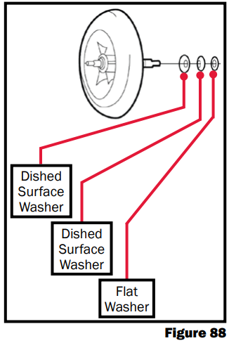
- Reinstall the protection cap. Reconnect the black (+) and brown (-) wires of the ignition coil to the C-plug harness’ yellow (+) and brown (-) wires. Reinstall the ignition coil and secure to the protection cap with the four ignition coil screws. Reconnect the ignition cables to the ignition electrodes.
- Fit the nozzle stand plate inside the cast aluminum blower casing and secure in place with the four nozzle stand plate screws. Reattach the fuel supply and return lines to the diesel-burner head.
- Follow the instructions for reattaching the diesel burner, in the detaching/reattaching section in this manual.


Diesel Burner Controller

The diesel burner controller operates all the components of the diesel burner head and safely shuts the heater OFF in the event of an overheat, flame-out, and low voltage condition. It also receives diesel burner operation status signals from the flame sensor, control thermostat, and DC high-limit thermostat.
| Note: Before troubleshooting the Diesel Burner Controller, verify that the Burner has voltage at Pin 4 as shown in Figure 119. There will only be voltage on that pin if the relay control board D5 light is illuminated |
Component Test:
The following conditions must exist prior to performing the following diesel burner controller circuit tests. If one of the conditions below does not exist, please contact Technical Support at 1 (800) 685-4298 for assistance.

Condition 1:
- A battery voltage level between 11.6-14 Volts DC must be present at the diesel burner controller during all testing. It may be necessary to perform a voltage check to ensure that this condition exists. To perform the voltage check, locate the controller’s B-plug and insert the probes of a DC voltmeter into the B-4 (+) and B-2 (-) pins.
Condition 2:
- A voltage level of between11.6-14 volts must be present at the diesel ON/OFF switch circuit of the diesel burner controller during all testing. It may be necessary to perform a voltage check to ensure that this condition exists. To perform the voltage check, locate the controller’s B-plug and insert the probes of a DC voltmeter into the B-1 (+) and B-2 (-) locations. Turn the diesel burner ON and observe the voltage levels.
Ground Circuit Test:
Locate the controller’s B-plug and C-plug. Insert the probes of a DC voltmeter into the B-4 (+) and C-5 (-) locations and turn the diesel burner ON. If a voltage reading does not register on the voltmeter, the controller must be replaced. If voltage is present, proceed to the next test.
Control Thermostat Circuit Test:
Locate the diesel-burner controller’s B-plug and C-plug. Insert the probes of a DC voltmeter into the C-1 (+) and B-2 (-) locations and turn the diesel switch ON. If a voltage reading does not register on the voltmeter, the diesel-burner controller must be replaced. If voltage is present, proceed to the next circuit test.
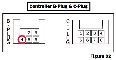
DC High-Limit Thermostat Circuit Test:
Locate the diesel-burner controller’s B-plug and C-plug. Insert the probes of a DC voltmeter into the C-4 (+) and B-2 (-) locations and turn the diesel switch ON. If a voltage reading does not register on the voltmeter, the diesel-burner controller must be replaced. If voltage is present, proceed to the next circuit test.
Motor Circuit Test:
Locate the diesel-burner controller’s B-plug and C-plug. Use a jumper wire to make a connection from the C-1 location to the C-7 location. Turn the diesel switch ON and insert the probes of a DC voltmeter into the C-2 (+) and C-5 (-) locations. If no voltage reading registers on the voltmeter, the diesel-burner controller must be replaced. If voltage is present, proceed to the next circuit test.
| Note: Be sure to remove the jumper wire that was used to make the connection from the C-1 location to the C-7 location. Failure to do so will result in an overheating condition during normal operation. |

Ignition Coil Circuit Test:
Turn the diesel switch OFF and locate the diesel-burner controller’s C-plug. Also, locate the VDC high-limit thermostat and disconnect it’s 2-way male plug from the (white plastic) 6-way female connector. Insert the probes of a DC voltmeter into the C-8 (+) and C-5 (-) locations and turn the diesel switch ON. If a voltage reading does not register on the voltmeter 18-25 seconds after the initial start-up, the diesel-burner controller must be replaced.
| Note: Be sure to reconnect the VDC high-limit thermostat’s 2-way male plug to the 6-way female plug. The diesel burner will not ignite during normal operation if the VDC high-limit thermostat is left disconnected. |
Replacement Procedure:
- Disconnect the Aqua-Hot from any and all power sources.
- Remove the B-plug and C-plug from the controller. Gently slide out the controller from the side of the diesel burner:

- Slide the new controller onto the side of the diesel burner.
- Reconnect the B-plug and C-plug.
- Test for normal operation.
| Note: Be sure to install the controller with the plug ports facing downward. Failure to do so will result in moisture collecting in the ports and potential damage to the controller’s internal circuitry. |
Fuel Pressure
Instructions for Checking Fuel Pressure:
Step 1: Remove the diesel burner
- Refer to the section on detaching the diesel burner on page 41.

Step 2: Install the fuel line bypass fittings onto the diesel burner.
- Locate the ¼” fuel tube unions on the bottom side of the diesel burner.

- Using a 13mm and a 9/16” wrench, remove the steel fuel lines from the diesel burner.

- Using a 13mm and a 9/16” wrench, install the fuel bypass fittings onto the diesel burner.
Step 3: Install the fuel pressure gauge
- Using a ⅝” and ¾” wrench, remove the fuel nozzle.

- Using a ⅝” and ¾” wrench, install the fuel pressure gauge.

Step 4: Running burner off an external fuel source
- Using an external fuel source and rubber fuel lines, hook the burner supply and return fuel lines up to run off the external fuel source.

- Turn the diesel burner ON, either on the switch panel or the coach control panel. A pressure will register on the fuel pressure gauge once the fuel solenoid opens (after approximately 10-20 seconds).

Aqua-Hot Maintenance
Monthly Maintenance:
Check the antifreeze and water heating solution to ensure that it is at the proper level by visually checking the solution level in the expansion tank. The level of the antifreeze and water heating solution within the expansion tank should only be checked when the Aqua-Hot is at maximum operating temperature. If additional antifreeze and water heating solution is required, fill the expansion tank to the “HOT” level mark. Reference Figure 105. Be sure to reference page 92 for the type of antifreeze and heating solution. Additionally, it is recommended that the diesel burner be fired and allowed to run monthly to keep it in good working order.

Annual Maintenance:
To keep the Aqua-Hot running smoothly, it is recommended to have the diesel burner tuned up annually or after the coach has been stored unused for a long period of time. A tune-up should consist of a new fuel nozzle and fuel filter, along with a thorough cleaning of the combustion chamber. To ensure maximum diesel burner performance, always use the recommended fuel nozzle and fuel filter when replacing these parts.

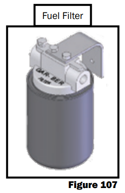
Aqua-Hot Maintenance Procedure
Step 1: Test Run the Diesel Burner
- Turn the diesel burner ON, either on the interior switch panel or coach control panel.
- After the diesel burner has ignited, inspect the exhaust for smoke.
- Shut the diesel burner off and wait for unit to completely shut down.
Step 2: Replace the Fuel Filter
- Locate the fuel filter
- Using hose pinch off pliers, clamp off both fuel lines going to the fuel filter. Reference Figure 108.
- Remove the old fuel filter. Replace the fuel filter with the proper replacement canister.
- Remove the hose pinch off pliers.
Step 3: Run the Diesel Burner
- Turn the diesel burner ON.
- After the diesel burner has ignited, let it burn for 1-2 minutes to purge the old fuel out of the nozzle holder, to prevent contamination of the replacement nozzle.
- Shut the diesel burner OFF, and wait for the unit to completely shut off.

Step 4: Remove the Diesel Burner
- Locate the diesel burner’s controller and disconnect both plugs.
- Using a 7/16” wrench, loosen the nuts securing each fuel line to the Aqua-Hot.
- The diesel burner is secured to the Aqua-Hot with two nuts that can be loosened and swung out of the way by using a 10mm socket wrench with a 10 inch long extension.


- Carefully pull the diesel burner away from the AquaHot 4 - 5 inches before rotating the burner, then remove completely as shown in Figure 115.

Step 5: Clean and Inspect the Combustion Chamber and Heat Transfer Tabs
- Remove the combustion chamber by loosening and removing the four nuts, securing the combustion chamber to the boiler tank and pulling it straight out, approximately 16 inches.
- Once the combustion chamber has been removed, use a long handled wire brush, and brush the heat transfer tabs to loosen soot deposits. Failure to do so will reduce the Aqua-Hot’s heat transfer capabilities.

- Inspect the Combustion Chamber assembly and Air Swirler for damage or signs of warping.
- Inspect the outer ring that the photo disc seats against for signs of warping.
- Inspect the back side of the Air Swirler for signs of warping between screws.

Step 6: Reinstall the Combustion Chamber
- Reinstall the Combustion Chamber assembly and the Air Swirler into the Aqua-Hot.

Step 7: Inspect the Diesel Burner
- Reinstall the Combustion Chamber assembly and the Air Swirler into the Aqua-Hot.

| Inspect the following: | |||
|
1. Electrodes
|
3. Photo Disc
|
5. Flame Sensor
|
7. Broken or cracked “Ears”
|
|
2. Fuel Pump
|
4. Harness & Ignition Coil Wires
|
6. Rubber Grommets
|
|
Step 8: Clean Ignition Electrodes and Flame Sensor
- Ignition Electrodes
- Polish away any carbon deposits that may have baked onto the metal tips of the ignition electrodes with a coarse sponger
- Flame Sensor
- For light dirt, dust, and/or carbon deposits, simply wipe off the flame sensor with a soft cloth.
- Should heavy carbon deposits be present, completely remove the flame sensor from the photo disc and clean with brake cleaner.

Step 9: Replace Fuel Nozzle
- Use a ¾” wrench to hold the fuel nozzle manifold hex, while loosening the fuel nozzle with a ⅝” wrench and remove.
- When replacing the fuel nozzle, be sure to tighten the nozzle, loosen it a ¼ turn, and then firmly re-tighten. This will establish a seated fit and avoid any leaks.

Step 10: Adjust Ignition Electrodes
- Using a 10mm socket, slightly loosen the retaining clamp bolt.
- Place the electrode adjustment gauge on the nozzle manifold hex and insert the metal tips of the ignition electrodes into the appropriate notches of the electrode adjustment gauge.
- Using a 10mm socket, tighten the retaining clamp bolt.
- Remove the electrode adjustment gauge.
| Note: Be sure not to over-tighten the retaining clamp bolt when readjusting the ignition electrodes. Overtightening the retaining clamp bolt will bend the retaining clamp and prevent the photo disc from floating freely. Not allowing the photo disc to float freely will cause poor combustion, and result in a smoky exhaust. A bent retaining clamp can be re-straightened with a punch and a hammer. Lay the clamp’s beveled side down on a solid flat surface and align the thick end of the punch at dead center. Tap the punch lightly until the retaining clamp returns to proper form. |

Step 11: Inspect the Photo Disc
- If the photo disc is not free-floating, the electrode clamp bolt has been over-tightened, and has bent the electrode clamp. Using a 10mm socket, remove the electrode clamp and re-straighten.
- Lay the clamp’s beveled side down on a solid flat surface and align the thick end of the punch at dead center. Tap the punch lightly until the retaining clamp returns to proper form.

Step 12: Reinstall the Diesel Burner
- Align the diesel burner with the Aqua-Hot, using the alignment tabs welded on the Aqua-Hot.
- Swing the eye-bolts around the “Ears” on the diesel burner and securely tighten, using a 10mm socket with a 10in long extension.

Step 13: Reconnect the Fuel Lines
- Align the fuel lines on the diesel burner with the fittings on the Aqua-Hot. Using a 7/16” wrench, tighten down both the supply and return fuel fittings.

Step 14: Plug in the Diesel Burner’s Controller and Mount
- Locate the diesel burner’s controller and connect both plugs.

Step 15: Reinstall the Aqua-Hot’s Access Cover
- Reinstall the Aqua-Hot’s access cover.

- Securely tighten the two bolts securing the access cover in place.

Step 16: Test for Normal Operation
- Turn the diesel burner ON and allow the diesel burner to run for a complete cycle, until it shuts off on its own.
- After the diesel burner has shut off, turn on the interior heat or run hot water until the diesel burner cycles back on. When the diesel burner cycles back on, check the exhaust for any signs of smoke.
Extreme Cold Weather Operation

120V AC Electric Element
Please note that the 120V AC Electric Heating Element is the Aqua-Hot’s secondary heat source for heating both the interior and/or the domestic hot water during low heating demand situations (such as when moderate ambient temperatures exist and/or when there is a low demand for domestic hot water). If the 120V AC Electric Heating Element is not providing enough heat, turn the diesel burner ON in conjunction with the 120V AC Electric Heating Element.
Diesel Burner
If the Diesel Burner fails to operate:
- Determine if the diesel fuel in the motor home is winter or summer fuel
- Verify that the diesel fuel is liquid and not jelled
- Make sure the electrodes are properly adjusted
- Determine when the last annual service was performed
Things to Check for Lack of Interior Heat:
- Diesel burner must be on
- Diesel burner operating properly
- Antifreeze concentration in the boiler tank must be between 30-50%
- Heating system must be properly installed according to the 250-D02 Installation manual:
- At least 5 heat exchangers installed in the interior of the coach
- Must be cold air returns installed for every heat exchanger (reference Figure 137)
- Heat exchangers should be mounted as close to the hot air outlet grill as possible (reference Figure 136)


Draining the Aqua-Hot
| Note: The Aqua-Hot 250D tank holds approximately 4.5 gallons of coolant fluid, not including coolant in the heat exchangers or coolant hoses throughout the coach. |

Drain Procedure:
- Remove the large access panel of the Aqua-Hot. It is held in place by two thumb screws. The valve is located in the bottom right-hand corner, (see Figure 139).
- Find the Fluid Drain Valve near the large thumbscrew at the bottom of the Aqua Hot system. See Figure 138.
- Connect a piece of ½” PEX-type tubing or rubber hose to the drain valve with a ½” NPT adapter. The hose should be long enough to reach a 5-gallon or larger bucket.
- Open the Fluid Drain Valve.
- Some coolant from the external hoses may drain into the bucket. If the bucket fills before the tank drains, shut off the valve and swap buckets for an empty one, then re-open the valve. Repeat this procedure until the tank is drained.


Filling and Purging
Before the first activation of the Aqua-Hot, fill the unit with antifreeze and water heating solution. Without the solution present, the Aqua-Hot will not operate. Follow the directions below to fill and purge the Aqua-Hot.
A 50/50 mixture of “GRAS” (Generally Recognized as Safe) approved propylene glycol antifreeze and distilled or deionized water is recommended. The mixture may be modified to provide the most adequate freezing, boiling, and rust/ anti-corrosive protection. Reference pages 92-93 for more information about antifreeze.
Procedure:
- Locate the fill valve at the zone port outlet (Figure 139).
- Make a ½” NPT connection from the propylene glycol source to the fill valve.
- Remove the access cover and locate the 3-way valve in the Aqua-Hot. Ensure that the sight glass is oriented as shown below. Reference Page 7, Figure 3 (Item #3) for the 3-Way Valve location.

- Activate the fluid transfer pump and begin filling the AquaHot through the fill valve.
- When the fluid level reaches the cold mark on the expansion bottle, deactivate the fluid pump.
- Close the fill valve and disconnect the pump.
- Reattach the access cover.
- Turn on the burner at the interior control panel and set the thermostat to its maximum temperature to allow for interior heating. Let the Aqua-Hot run for at least 20 minutes to ensure that any air in the heating loop has been purged. If necessary, top off the propylene glycol solution at the fluid expansion bottle.

General Troubleshooting
Purpose:
This section serves to solve common operational problems, to reduce down-town and unit repair costs, by fixing the simplest problems first.
Troubleshooting Procedure:
If your 250-D02 has been unused for an extended period of time, performing the annual service may resolve many problems. Instructions for the annual service are on Page 75 or may be performed by an Aqua-Hot Factory Certified Service Center. They can be found on the website at www.aquahot.com.
- Ensure that the Aqua-Hot is supplied with electrical power.
- Ensure there is an adequate supply of fuel (at least ¼ tank).
- Ensure that the Aqua-Hot boiler tank has an adequate supply of antifreeze and water heating solution by checking the level at the expansion bottle. If the level is low, reference the maintenance section of this guide for refilling instructions.
- Verify the functionality of any in-line fuses connected to the Aqua-Hot. Replace these fuses if necessary.
- Ensure that all coach-side hot water faucets are closed.
- Locate the relay control board within the Aqua-Hot unit. See Page 9 to identify this component.
- Verify that all of the fuses in the relay control board are in good working condition. Replace any non-functional fuses.
- Visually inspect the interior cabinet of the Aqua-Hot unit, searching for any damaged or disconnected wires. Reconnect or repair any damaged wires.
- The 250-D02 contains a 20A fuse as part of the wiring harness. Check that this fuse has not been burned out.
- Locate the left high-limit thermostat and follow the procedure on Page 21 to troubleshoot this component.
- Locate the right high-limit thermostat and follow the procedure on Page 21 to troubleshoot this component.
- Visually inspect the exhaust system of the Aqua-Hot to ensure that it has not been damaged or removed.
- Test for unit operation:
- If the burner fails to operate, proceed to Page 90 to begin the diesel burner troubleshooting.
- If the burner begins to operate at this stage, choose a troubleshooting guide below based on the issue.
Lack of, or Uneven, Hot Water
A lack of hot water, or uneven delivery of hot water (hot water that contains cold spots), is typically due to a failure of one more of five components: the shower head, the stir pump, the three-way valve, the low-temperature cutoff thermostat, or the tempering valve.
- Shower Head
- It is possible that the shower head in the coach is drawing hot water too quickly from the Aqua-Hot, overtaxing the unit resulting in hot water delivery problems. The shower head should be limited at 1.5GPM max.
- Stir Pump
- Reference Page 27 to troubleshoot the stir pump.
- Three-Way Valve
- Reference Page 24 to troubleshoot the three-way valve.
- Low-Temperature Cutoff Thermostat
- Reference Page 22 to troubleshoot this component.
- Tempering Valve
- Reference Page 26 to troubleshoot the tempering valve.
Once these components have been diagnosed, restart the Aqua-Hot and allow it to heat to operating temperature. Draw hot water to determine if the problem has been addressed.
Lack of Interior Heat
A lack of interior heat with a functioning burner can be attributed to many potential issues in the Aqua-Hot. Diagnosis will involve three stages. Stage 1 will outline common reasons for overall unit non-function that exists outside of the unit. Stage 2 will diagnose common issues inside the unit, including lack of burner operation. Stage 3 will address specific reasons for a lack of interior heat. It is very important that troubleshooting proceed in the order outlined below. The issues most common with a lack of heat are:
- A non-functional three-way valve
- A seized circulation pump
- Air trapped in the coach heating loop
- A malfunctioning low-temperature cutoff thermostat
Stage 1:
- The coach is supplied with power
- The Aqua-Hot has an adequate supply of fuel
- All coach-side fuses are functional and able to supply power
- All water sources connected to the coach are shut off
- All fuses on the relay control board are functional
- The overflow bottle is filled to at least the COLD mark
Stage 2:
- Visually inspect the interior cabinet of the Aqua-Hot unit, searching for any damaged or disconnected wires. Reconnect or repair if necessary.
- The 250-D02 contains a 20A fuse in the wiring harness. Make sure this fuse has not burned out.
- Make sure the high-limit thermostats are not tripped or defective. Replace if necessary.
- Test for unit operation.
- If the burner fails to operate, follow the procedure on Page 90 to begin diesel burner troubleshooting.
Stage 3:
- Begin troubleshooting the three-way valve. See Page 24.
- Reference Page 22 to diagnose the Low-Temperature Cutoff Thermostat.
- Locate the circulation pump within the Aqua-Hot cabinet. It should begin operating immediately when the heater starts up. If the pump does not begin to operate, see the procedure on Page 27 for troubleshooting.
- Locate all of the heat exchangers within the coach and determine if any of them are outputting heat.
- If at least one heat exchanger is outputting heat, an air bubble may be preventing the flow of the antifreeze and water heating solution.
- It may be possible to resolve this issue by allowing the circulation pump to run continuously, checking the heat exchangers periodically to determine if they have begun to function. See Page 85 for the heating loop purge procedure.

250-D02 Unit Smoke
Purpose:
It is possible that the Aqua-Hot 250-D02 may smoke upon first start-up. There are many possible causes for smoke as listed below.
If the unit has sat for an extended period of time unused, please perform the annual service.
- Clear exhaust or no smoke
- The unit is operating correctly
- Blue/White smoke
- Fuel Solenoid
- Nozzle Tower
- Control Thermostat
- Short-cycling
- Black smoke
- Low voltage
- Exhaust system damage
- Air intake
- Burner is improperly seated
- Combustion chamber damage
- Fuel delivery system
As such, it is necessary to select the correct troubleshooting procedure to solve the issue quickly.
Blue/White Smoke
Smoke During Start-Up or Shut-Down:
- Ensure that the unit is not short-cycling (rapid power-up and shut-down) during its start-up procedure. This can be caused by:
- A faulty switch
- Damaged wiring
- A malfunctioning control thermostat
- Diagnose the control thermostat by testing for continuity. Reference Page 17 for the procedure. Test the unit after this is complete.
- Detach the diesel burner from the Aqua-Hot (see Page 41) to gain access to components for testing.
- Remove the igniter coil flange to gain access to the fuel tower, nozzle, igniter module, and flame sensor.
- Visually inspect this sub-assembly, looking for any damage or leak locations.
Smoke During the Burn Cycle:
- It is possible that the electrodes of the igniter module have been knocked out of adjustment.
- Follow the directions on Page 41 to gain access to the diesel burner head.
- Using a Webasto electrode gauge, make sure the tips of the electrodes fit into the grooves of the gauge.
- Air may be present in the fuel system, resulting in the uneven delivery of fuel to the nozzle and causing excessive smoke. Check the fuel delivery system for any damage or loose clamps which may introduce air into the fuel line.
- Check the ignition coil for proper operation.
Black Smoke:
- Ensure that the Aqua-Hot is receiving 12V DC power from the coach.
- Inspect the exhaust system for any damage or restrictions. Remedy these issues.
- Remove the access cover of the unit.
- Attempt to shake the burner sub-assembly. If the burner moves, it has been improperly seated. Follow the directions on Page 41 to remove and reinstall the diesel burner.
- If at this stage the burner is still producing black smoke, it is recommended that the annual service be performed. See Page 75 for the procedure.
- Visually inspect the inside of the combustion chamber for any warping or apparent heat damage.
- Remove the diesel burner from the Aqua-Hot - see Page 41.
- Remove the combustion chamber to gain access to the heat exchanger as shown in Figure 141.
- Using a wire brush, scrub the heat exchanger inside the Aqua-Hot as shown in Figure 141.
- If at this stage, black exhaust smoke is not remedied, contact the Aqua-Hot Technical Support at 574-AIR-XCEL (574-247-9235) or locate your nearest authorized service center.
Diesel Burner Troubleshooting
This section will assist in troubleshooting the Aqua-Hot diesel burner. If additional assistance if needed, please contact the technical support department at 574-AIR-XCEL (574-247-9235).
Troubleshooting Procedure:
- If this unit has been inactive for an extended period of time, perform the diesel service prior to beginning these troubleshooting steps. The annual service will typically resolve many common issues which may impede unit operation.
- Locate the fluid overflow bottle and ensure that it is filled to at least the COLD mark.
- Remove the cabinet access panel from the front of the Aqua-Hot.

- Verify that the 20A fuse included as part of the diesel harness is functional. Replace if necessary.
- Move the burner switch on the interior switch panel to the ON position.
- Make sure the interlock switch is depressed.
- Verify that 12V DC power is present at Pin B4 of the diesel burner controller.
- If 12V DC is not present, check the control thermostat for functionality by following the directions on Page 17.
- Locate the left and right high-limit thermostats and press the red center button on both thermostats to reset.
- Test for continuity on both thermostats. Both should have continuity after reset. If one does not have continuity, follow the instructions on Page 21 to replace one or both.
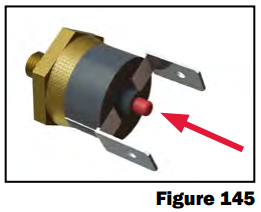
- Check the ignition electrodes for functionality by following the directions on Page 53.
- Troubleshoot the ignition coil referencing the procedure on Page 55.
- Ensure that the flame sensor is functioning properly by completing the procedure on Page 51.
System Schematics
