Xantrex Owners Guide
Access a printable PDF copy at this link: Xantrex Owners Guide.pdf


ABOUT THIS GUIDE
Purpose
The purpose of this Owner's Guide is to provide explanations and procedures fro operating, maintaining, and troubleshooting a Freedom SW Inverter/Charger for recreational vehicle and commercial applications.
Scope
The guide provides safety guidelines as well as information about operating and troubleshooting the installation the inverter/charger. It does not provide details about particular brands of batteries. You need to consult individual battery manufacturers for this information.
Audience
The guide is intended for users and operators of the Freedom SW Inverter/Charger.
This guide is intended for qualified personnel. Qualified personnel have training, knowledge, and experience in:
- Installing electrical equipment and power systems (up to 1000 volts.)
- Applying all applicable installation codes.
- Analyzing and reducing the hazards involved in performing electrical work.
- Selecting and using Personal Protective Equipment (PPE) and following safety work code practices. See NFPA 70E or CSA Z462 or EN 50110-1.
Related Information
You can find more information about Xantrex products and services at http://www.xantrex.com/.
IMPORTANT SAFETY INSTRUCTIONS

Safety Information


Precautions When Working With Batteries

Precautions When Preparing to Charge

Precautions When Placing the Unit

Regulatory

EMI Information to the User

End of Life Disposal


INTRODUCTION

Materials List

Key Features
The Freedom SW is a true sine wave inverter/charger that can be used for recreational vehicle and commercial applications. The Freedom SWs are designed to operate with a wide variety of generators and are cable of operating in parallel with a generator for short durations to assist with starting large loads. The freedom SW is a convenient combination of an inverter multistage battery charger and transfer switch in one electronic device.
- As an inverter, the Freedom SW provides true sine wave power for your microwave, entertainment system computer, and other loads. This power is identical to the AC source provided from the utility grid (power company).
- Some of the benefits of true sine wave power include consistent cooking in your microwave, handling of sensitive loads such as your TV set, dimmer switches, and appliances with speed controls.
- Highly versatile platform capable of series stacking for 120/240V line configurations (Product Numbers: 815-3012, 815-3024) and parallel stacking to increase power levels.
- High efficiency true sine wave output to power sensitive electrical and electronic equipment.
- Surge capacity to start difficult loads like refrigerators or A/C compressors.
- Power factor-corrected (PFC) input minimizes AC input current required for charging, increasing AC pass-through capacity.
- As a charger, it has high output, multistage charging capability minimizing charging time.
- Capable of operating from 50 Hz and 60 Hz power source by extending AC qualification frequency range. See ACIn Settings on page 55.
IMPORTANT: With a dual line configuration (Product Number: 815-2024, 815-3024), only the Line 1 Input needs to be energized in order to qualify the AC. Line 2 Input does not have to be powered with a single phase system
- Temperature-controlled, variable-speed internal cooling fans. The fans turn on when the internal temperature reaches 45ºC (113ºF) and reaches maximum speed at 70ºC (158ºF). The fan turns off when the internal temperature falls to 40ºC (104ºF).
- Designed with serviceability in mind via Xantrex Authorized Service Centers (ASC).
- The Freedom SW is Xanbus-enabled which allows network compatibility and communication with other Xanbus-enabled devices.
- The Freedom SW (Product Number: 815-3012_02) is RV-C protocol-enabled which allows network compatibility and communication with other RV-C devices.
Key Features Explained
Built-in Charge Formulas
For the unit to perform at the highest level, the batteries must be charged correctly. The Freedom SW has optimized algorithms for flooded, gen, and AGM batteries.
Battery Temperature Sensor
Since battery temperature is a key factor in correct charging, the charging formula must be adjusted (automatically and in real time) according to the actual battery temperature to ensure that batteries are fully charged, but not overcharged. For this reason, a battery temperature sensor is included with your Freedom SW and has temperature compensated the charge formula.
Manual Equalization
Over a period of time, the cells in a flooded battery can develop uneven chemical states. This can result in a weak (undercharged) cell which, in turn, can reduce the overall capacity of the battery. To improve the life and performance of a non-sealed, flooded battery, the Freedom SW's multistage charging cycle includes a manual equalize mode that can be used, if recommended by the battery manufacturer.
Dead Battery Charging
Another feature that the Freedom SW includes is dead battery charging. The Freedom SW-unlike many chargers- has the ability to recharge batteries even if the battery voltage is ver low at 5 volts for 12VDC models (Product Numbers: 815-2012, 815-3012, and 815-3012_02) and at 12 volts for 24 VDC models (Product Numbers: 815-2524_02, and 815-3524_02).
Load Management
The Freedom SW has a built-in transfer relay that connects your inverter output or AC input from the utility grid or generator to your loads. Because the usual AC power sources such as campground outlets or small generators often have limited current availability., having the capability to manage your AC loads is extremely valuable.
The Freedom SW provides a number of features t facilitate this:
- The charger is power factor corrected to use AC current as efficiently as possible. Minimizing the AC current used b the charger means more current is available for your AC loads.
- Freedom SW has a power share feature which prioritizes your AC loads by reducing the charge current in an attempt to limit the total input current to less than the breaker settings.
Occasionally, AC input sources have low voltage. To avoid loading these weak sources any further, the charger automatically reduces its AC current draw as the AC voltage approaches the minimum acceptable level.
Stacking
Supports stacking of two inverter/chargers to increase capacity. This also requires the installer to select a Primary and Secondary in order for the inverters to stack. Two configurations of stacking are supported: Parallel stacking and Series stacking.
Parallel Stacking
Parallel stacking allows two inverter/chargers to operate in parallel thereby doubling the capacity in inverter mode. The two inverters communicate over the network and intelligently share the load and ot balance the load between the two units. The primary Freedom SW broadcasts pulses on the communication network (Xanbus or RV-C) to synchronize operation between the other paralleled unit. When AC loads are present, both units produce power, effectively sharing the load. When Load Sense is enabled, only the primary unit produces the AC output.
Series Stacking
Two units can be configured to generate 120/240 Split-phase power for load configurations that require both 120 and 240 volts. In this configuration, the AC source must be split-phase as well. Applicable to Freedom SW (Product Numbers: 815-3012, 815-3024 only).
Stack Charging
Two Freedom SWs synchronize charging stages to ensure efficient charging of the battery bank. When a single unit transitions from bulk to absorption so do all other units. In absorption, all units must complete the absorption stage before transitioning to the next stage. Note that units do not load share when charging except during the bulk stage. The Freedom SWs stop sharing charge current just before completing the bulk stage. The units do not share charge current during the absorption and float stages.
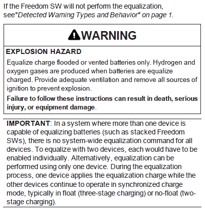
Each unit charges batteries based on the Max Charge Rate setting and active internal (temperature-based) ratings. If equalization is enabled on one or more devices capable of equalization charging,only those devices perform an equalize cycle after absorption. Other devices transition to float (if three-stage charging is selected) or transition to AC pass-through (if two-stage charging is selected).
Generator Assist
The Freedom SW inverter/chargers can operate in tandem with a generator (or shore power) to temporarily assist power loads with large start-up demands such as air conditioners, water pumps etc.
When the Gen Support mode is enabled and the generator's or shore power's current capacity defined (in amps) is above the GenSupport current threshold, the inverter will come on-line and assist the generator or shore power with starting and operating the load (drawing power from the battery). The battery bank must be well charged in order for the inverter to engage this mode. For more details, see Gen Support on page 55.
Basic Protection Features
The Freedom SW has the following protection features:
- Over temperature shutdown for critical components such as the transformer and the power board.
- Battery temperature sensor (BTS) failure/battery temperature out-of-range fault protection.
- DC output over voltage protection during charge mode
- AC transfer relay failure detection
- AC output overload and short circuit protection during invert mode
- AC backfeed protection
- Short circuit protection for the BTS and communication connector ports including protection from incorrectly inserting the remote panel communication cable plug into the BTS port and vice versa
The Battery Temperature Sensor (BTS) provides these protection features:
- Battery over temperature charging protection preventing battery charging at 60ºC (140ºF) or higher
- Charging voltage compensation based on the temperature of the battery where the BTS is connected
Freedom SW Supplied Accessories

Other Accessories

MECHANICAL FEATURES
Note: There are eight model of the Freedom SW. Throughout the guide, Freedom SW units may be referred to according to these categories. For example, Freedom SW 110VAC models apply only to models under the 110 AC Voltage category.

Freedom SW Front and Side Panels
Before you begin to operate the Freedom SW, review the front panel features shown in Figure 4 and described in the next table. A detailed view of the LEDs and buttons on the front panel is shown "Freedom SW Front and Side Panels" above and described in the table next to it.


Freedom SW AC and DC Side Panel
The DC side of the Freedom SW has the DC equipment ground lug, the positive (+) battery terminal, and the negative (-) battery terminal plus the remote network com port and battery temperature sensor com port.

OPERATION
Note: There are eight models of the Freedom SW. Throughout the guide, Freedom SW units may be referred to according to these categories. For example, Freedom SW 110V AC models apply only ot models under the 110 AC Voltage category.

Start Up Behavior
When the Freedom SW is powered up or has been reset, all of the front panel LEDs turnon and remain on for a minimum of five seconds. During the interval, the fans are also turned on as the unit executes internal diagnostics.
Out of the box from the factory, when the Freedom SW is powered up (that is, when AC and DC power sources are connected) for the first time, the inverter function is disabled by default. After powering up, the INVERTER ENABLE button can be used to enable or disable inverter function. See Inverter Operation Using the Front Panel on page 17.
Storing Inverter State Feature*
You can enable or disable a feature called StoreInvState which, when enabled remembers the state of the inverter function prior to a power down (that is, when AC and DC power sources are disconnected) or prior to Standby (Power Save) mode.
When the Freedom SW is powered up again or put back on Operating mode, the inverter function reverts back to its prior stat. See To store the state of the inverter to memory: on page 47. This feature is disabled by default.
*This feature is available only to Freedom SW 24V 2024 (PN: 815-2024)
Enable versus Disable
When a function is enabled, it is allowed to occur but other conditions may have to be met before the function actually works. For example, the charger function on the Freedom SW may be enabled, but will not charge the battery unless qualified AC power is present. For Xanbus-enabled Freedom SW models, see Enabling a function and Disabling a function on page 1.
IMPORTANT:
Review the Important Safety Instructions on page 2 before operating the inverter/charger.
Inverter Operation Using the Front Panel
IMPORTANT:
Review the Important Safety Instructions on page 2 before operating the inverter/charger.
Once the inverter/charger is installed, you can operate it in invert mode.
To operate in inverter mode from the front panel:
1. Press the INVERTER ENABLE button on the Freedom SW on the front panel. The INVERTER ENABLED LED turns on and connected loads will be energized.
2. Note that if AC is present and being passed through, the INVERTER ENABLED LED will still turn on to indicate inverter mode has been enabled. However, AC will continue to be passed through to the loads until conditions exist that cause AC to be disqualified, in which case the unit will transition to invert mode and power up critical loads.
3. Connect AC input power.
The charger automatically stats up when qualified AC power is connected.
4. Disconnect AC power from inverter input by opening the breaker or disconnect.
5. Place a load on the inverter. For example, plug a 100-watt light bulb into an outlet that the inverter is powering. Press the INVERTER ENABLE button on the Freedom SW. The INVERTER ENABLED LED turns on. The inverter should run the load using battery power.
6. To test the charger, reconnect the AC input power to allow AC to the AC input. The AC In/Charging LED should start flashing after a brief delay. Any AC loads previously powered by the inverter will also work at this time.
Note: With dual input, only AC Input L1 needs to be powered for the unit to operate.
7. Remove the AC input power. The inverter/charger should transfer to invert mode immediately. (The transfer relay will make a clicking sound and the INVERTER ENABLED LED will turn on.) Loads should continue to operate uninterrupted.
If any part of this test fails, determine the cause before using the unit.
8. Monitor the Freedom SW Front Panel.
The indicator LEDs on the front panel show you the operating status of the Freedom SW. A description of the LEDs is provided in.
If none of the front panel LEDs are on, see Troubleshooting on page 65.


Faults and Warnings
A fault affects the operation of the unit. A manual fault requires user intervention by clearing the condition and then pressing the CLEAR FAULT RESET button on the inverter/charger's front panel.
A warning alerts you to a condition that could possible affect operation of the unit.
IMPORTANT
If you are having problems with any of your loads, refer to Inverter Applications on page 70.
Operating Limits for Inverter Operation
Temperature
The Freedom SW inverter/charger will operate (in invert mode) at rated power continuously and then at derated power at a higher ambient temperature (such as at 40ºC). See Specifications for full details. In higher ambient temperatures, if the loads draw full power for an extended period of time, the unit may shut down to protect itself against overheating.
The Freedom SW features a surge rating of 200% of rated power for five seconds at 25ºC. Operating the inverter/charger in conditions outside of power and temperature limits, however, will result in thermal shutdown and/or significantly decreased performance. In addition, operation in this range is outside the ratings covered by the regulatory approvals of the product.
Difficulty on starting loads
The inverter/charger should be able to operate all AC loads rated at or below its power rating. Some high horsepower induction motors used in pumps and other motor-operated equipment require very high surge currents to start, and the inverter/charger may have difficulty starting these loads.
If you have problems starting certain loads, ensure that :
- Battery connections are tight and clean.
- DC cabling is no longer than the recommended length. Refer to the Installation Guide (document number: 975-1188_01_01) for this information.
- AC wiring is of recommended size. Refer to the installation Guide (document number: 975-1188_01_01) for this information.
- Battery is of sufficient capacity and is fully charged.
NOTE: Many 12 VDC inverter battery banks have a capacity between 400-800 Ah and many 24 VDC inverter battery banks have a capacity between 200-400 Ah. Refer to the Installation Guide (document number: 975-1188_01_01) for sizing requirements.
Operating Limits for Charger Operation
By default, the maximum charger output current is the rated charger output current.
The charger can operate within an AC input range of 85-135 volts. The default settings are 95 and 135, which are the ACIn Lo Volt and ACIn Hi Volt respectively. The ACIn Lo Volt setting has a range of 78-115 volts and the ACIn Hi Volt setting has between 125-140 volts.
Note: Applicable to Freedom SW (Product Numbers: 815-2524_02, 815-3524_02).
The charger can operate within an AC input range of 170-270 volts. The default settings are 202 and 260, which are the ACIn Lo Volt and ACIn Hi Volt respectively. The ACIn Lo Volt setting has a range of 170-220 volts and the ACIn Hi Volt settings has between 240-270 volts.
AC Frequency
The charger can also be configured to accept and operate from a wide AC source frequency of 44-70 Hz. Therefore, the Freedom SW can charge your batteries even when incoming AC voltage is less than ideal. The default settings are 55 and 65 Hx, which are the ACIn Lo Freq and ACIn Hi Freq settings respectively.
Power sharing
The Freedom SW charger uses incoming AC or shore power (see following note) to charge the batteries. The charger shares incoming AC power with AC loads on Line 1 only. The AC loads have priority, which means that the charger will reduce its output with large AC loads and increase the output again when the AC load decreases. The regulatory maximum for continuous AC loads is 80% of the breaker rating (see "AC 1 Breaker" on page 51) that the loads are connected to. Freedom SW senses pass-through current going to the AC load. The difference between the pass-through (load) and 80% of the AC1 Breaker setting is the current that is available for charging the batteries.
For example, if the AC input of the Freedom SW is from an AC panel with a 30-amp breaker, the AC 1 breaker setting should be selected as 30 amps. Based on this, the charger will control the charge current so that the total current draw is equal to or less than 24 amps in this case. Should the load current be more than 24 amps, the charger output will reduce to 0 amp, but the Freedom SW will continue to supply the loads. The Freedom SW will continue to pass-through power to the loads, even if the load current exceeds the AC 1 Breaker setting. In this case, it will be up to the user to remove/disconnect loads if tripping the AC input breaker supplying the Freedom SW is to be avoided.
Note: The AC 1 Breaker setting can be changed using the Xanbus System Control Panel (PN: 809-0921) or a compatible RV-C system device controller, if available for Freedom SW 3012 RVC (PN: 815-3012_02).
3A XANBUS OPERATION

Operating the Xanbus-Enabled Freedom SW with the SCP

Using the Xanbus SCP
As shown in "operating the Xanbus-Enabled Freedom SW with the SCP" above, the SCP has these important features:
Display Screen
System information is shown on the display screen with an adjustable backlight.
Indicator LEDs
Four indicator LEDs on the front panel indicate the operating status of the Xanbus system.
Push buttons
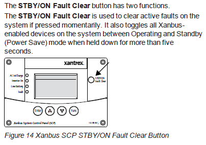
Four push buttons allow you to select device menus and change or display settings. The red STBY/ON Fault clear button toggles the SCP and Xanbus-enabled devices between Operating mode and Standby (Power Save) mode, if held down for more than five seconds. The button can also be used to clear any active faults or warnings by momentarily depressing the button.
System Control Panel
The Xanbus System Control Panel (SCP) provides configuration and monitoring capability for all Xanbus-enabled devices on the network. All changes to the configuration of the Freedom SW are mode with the SCP.
The front panel of the Freedom SW provides limited control, including reset; charger enable and disable; and inverter enable and disable.
Enabling a function
When a function is enabled, it is allowed to occur but other conditions may have to be met before the function actually works. For example, the charger function on the Freedom SW may be enabled, but will not charge the battery unless qualified AC power is present.
Disabling a function
When a function is disabled, it is not allowed to occur and if it is already occurring, it is terminated immediately. Regardless of other conditions, the function will not work. For example, even if AC power is present, if the charger function is disabled, the Freedom SW will not charge the battery.


SCP Navigation Startup Screen
This screen is shown when the Xanbus SCP first receives power from the Xanbus network.

Viewing the SCP Home Screens
The top level screens on the Xanbus SCP are the startup screen, the System Status screen ("Operating the Xanbus-Enabled Freedom SW with the SCP" on page 21) and the device Home screen. After power is applied and the startup screen appears, the Xanbus SCP displays the System Status screen. You can view the device Home screen for the Freedom SW and other devices in the system by pressing the up and down arrows.

System Status Screen
The System Status screen appears after the startup screen. It displays aggregated status information for the entire power system. For example, a single system might have two Xanbus network-connected Freedom SWs, one Xanbus AGS module, and one Xanbus SCP all connected to a single battery bank.
The System Status screen always features a menu arrow pointing to the Enter button. Pressing Enter takes you to the Select Device menu screen. For more information, see "Reading the System Status Screen" on page 26.
NOTE: If you are uncertain which Xanbus SCP menu screen you are viewing, you can return to the starting point-the System Status screen-by pressing the Func button repeatedly until the screen stops changing.
Select Device Screen
As mentioned, this screen appears when the Enter button is pressed from the System Status screen. It lists all Xanbus-enabled devices including options to select System Settings and Clock.

Device Setup Screen
The Device Setup screen is shown when a Xanbus-enabled component is selected from the Select Device screen. For example, below is an example of a Device screen for the Freedom SW 3012 inverter/charger. Device Setup menus display status information and changeable settings. Changeable settings are identified by the square brackets [] around values in the right-hand columns.
To display the Setup menu for a device:
- Highlight the device name on the Select Device menu screen and press Enter.
-Or-
From the device Home screen, press Enter.

Soft Key Navigation
Soft keys are the objects on the fifth line of the System Status screen. The soft keys have arrows that point to a corresponding physical button such as the Enter, Up arrow, Down arrow, and Func buttons. They are called s such because they perform functions in conjunction with pressing the corresponding SCP button that each arrow points to.


Viewing the Firmware Revision Number

Setting the Time and Date

Using the STBY/ON Fault Clear Button
Reading the System Status Screen

Reading the Freedom SW Device Setup Screen


Configuring the Xanbus Enabled Freedom SW using the SCP

System Menu Map
"Configuring the Xanbus-Enabled Freedom SW using the SCP" above provides a map of how the SCP screens and menus are organized. The order of devices appearing on the SCP will vary, depending on the order in which they've been connected to the network.

Viewing the System Status Screen
The System Status screen displays system activity. The information appearing on the System screen varies with the status of the inverter/charger. See "Configuring the Xanbus-Enabled Freedom SW using the SCP" above. Go back to "Configuring the Xanbus-Enabled Freedom SW using the SCP" above for an explanation of the different states of the inverter/charger. For example, "Bulk System Screen (Example)" below shows the Freedom SW in the bulk stage of charging.

Viewing the Select Device Menu
The Select Device menu is where you can view a list of all the Xanbus-enabled devices in your power system.
At least two devices are sure to appear together with System Settings and Clock-the Freedom SW Inverter/Charger and the Xanbus SCP. Other devices such as the Xanbus AGS and the Freedom Sequence Intelligent Power Manager appear only when they are connected and installed.

Selecting the Freedom SW from the Select Device Menu
To view the Freedom SW Setup menu screen:
- Follow the procedures on "Configuring the Xanbus-Enabled Freedom SW using the SCP" on the previous page.

You can view and change Freedom SW settings from the Setup menu screen. The Basic Settings and Advanced Settings bring up their menu screens for which other configurable settings can be found.
Changing Configurable Settings From The Device Setup Menu Screen
The Freedom SW can only be configured using the Xanbus SCP. Follow the procedure in "Configuring the Xanbus-Enabled Freedom SW using the SCP" on the previous page to bring up the device setup screen for the Freedom SW inverter/charger.

These configurable settings are:
- Advanced settings
- Inverter
- Search mode
- Charger
- Force charge
- Equalize
- Desired mode
- Clear fault settings
- View device info
- Basic settings
Only nine of these settings are displayed at a time. The Advanced Settings (Line 6) is not initially listed and only lines 7 through 15 appear. When the Advanced Settings is listed, it will appear on top of the list for configurable settings and the setup screen will display lines 6 through 14.
See "Configurable Settings" on the next page for information on each setting.
To select and change a configurable setting:
1. On the setup menu, press the Down arrow (or Up arrow) button to highlight the setting you want to change.
2. Press Enter to highlight the current value of the setting.
3. Press the Up arrow or the Down arrow button to change the value. Hold down the button to scroll through a large range of values quickly.
The previously set value (or default value) appears with an asterisk (*) beside it.
4. Press Enter to select and confirm the value.
5. If you have another setting to change, press Func until the Xanbus SCP displays the desired screen or menu.


Using Search Mode
Why use Search mode?
Search mode allows the inverter to selectively power only items that draw more than a certain amount of power, which can result in power savings. The Freedom SW has a no-load power draw of about 28 watts. Search mode operates differently in single-unit and multi-unit installations.
Single units
When a single Freedom SW has search mode enabled, the inverter sends electrical search pulses through its AC output. These search pulses look for connected AC loads. The delay between search pulses look for connected AC loads. The delay between search pulses is set using the Search Delay setting. After a load larger than the Search Watts setting is detected, the inverter starts producing AC output.
Double units
When configured for 120/240-volt series stacking, each inverter/charger operates independently in search mode and attempts to detect loads connected to its terminals only.
To use search mode in parallel stacking, the Master unit must have Search Mode disabled. The Slave unit must have Search Mode enabled.
NOTE: The Slave unit continuously monitors the output of the Master unit. If the Master unit has more than 60% of the rated load (for example, 1800 watts on Freedom sW 3012), the Slave unit will assist the Master and the two will share the load equally. Should the load on the Master drop below 20% of rated load (600 watts for Freedom SW 3012), the Slave unit disengages and returns to a waiting state.
When to set up Search mode
The search mode feature is only valuable if the inverter can spend a fair amount of time "sleeping" each day. Therefore, if search mode is to be used it must be adjusted properly. The initial adjustment should be made so that the inverter comes on only when needed.
Certain types of loads can cause search mode to work unexpectedly. These types of loads are described in "Inverter Applications" on page 1. If these kinds of loads are in the system, follow the suggestions given to eliminate the problem.
If the problem loads cannot be eliminated, there are two work-around solutions:
1. Disable search mode from the main Freedom SW Setup menu, causing the inverter to always remain at full output voltage.
2. Use a search-friendly companion load whose only purpose is to be switched on to wake up the inverter to power the load that is unable to bring the inverter out of search mode.
NOTE: Search mode, by function, cannot work with clocks and timers or devices that need power 24 hours a day. Examples of devices that need power 24 hours a day. Examples of devices with timers include video recorders, coffee makers with brew timers, refrigerators, and freezers with defrost timers. Examples of devices that need power 24 hours a day include telephone answering machines, alarm systems, motion detection lights, and some thermostats.
When the inverter is searching the output for loads, lights that have a wattage lower than this setting may flash momentarily.
Equalization Procedure
To start equalizing the batteries, do one of the following:
- Apply AC voltage and ensure that the inverter/charger transfers AC and starts charging.
- On the Xanbus Setup menu, highlight Equalize and select Enable.
The unit will proceed and execute a complete bulk and absorption charge before transitioning to equalize.
IMPORTANT: The inverter/charger will not perform equalization if AC is not present, the charger is disabled, or the selected battery type does not support equalization. If any of these cases happen, a warning is issued.
Changing Basic Settings
The Freedom SW configuration settings can be viewed in basic format (see "Configuring the Xanbus-Enabled Freedom SW using the SCP" on page 28). The basic settings include configuration items you may have to adjust routinely, or as part of initial setup. It provides access to basic control of the inverter/charger.
Temporary versus permanent
The Freedom SW unit stores its configuration in its onboard memory which holds configuration values even during power cycling or restart events. The Freedom SW allows the user to make changes to the configuration settings at any time the unit is powered and communicates with the SCP or a Xanbus configuration tool. This is true for Basic Settings as well as Advanced Setting ("Changing Advanced Setting" on page 36).
Any configuration setting changes will be temporary, that is, they will be lost after a power cycle or restart. In order to make the setting permanent, they must be saved in the onboard memory by placing he unit in Standby (Power Save) mode. For instructions on how to put the unit in Standby (Power Save) mode, see "Configuring the Xanbus-Enabled Freedom SW using th SCP" on page 28. While the unit is in the Standby (Power Save) mode the configuration changes will be immediately saved in the onboard memory. For more information on operating states (modes), see "Configuring the Xanbus-Enabled Freedom SW using the SCP" on page 28.
To select the Basic Settings menu screen:
1. On the FSW3012 00: Setup screen in the case of Freedom SW 12V 3012 ("Configuring the Xanbus-Enabled Freedom SW using the SCP" on page 28), press the Down arrow button until Basic Settings is highlighted.

2. Then, press Enter to display the FSW3012 00: Basic screen which is the basic settings menu screen.
3. Press the Up and Down arrow buttons to move between selectable fields.
- Battery type
- Battery capacity
- Maximum charging rate
- Charging cycle
- Recharging volts
- AC In breaker rating
- Low battery cutout value
See "Basic Settings" on page 35 for information on each setting.
An overview of the Freedom SW menu structure is shown below. The SCP displays the Freedom SW basic settings menus.


Changing Advanced Settings
The advanced settings option gives your access to the full range of Freedom SW settings, including everything displayed on the basic menu. As a safeguard against unintended advanced configuration, the Xanbus SCP displays the basic settings by default. To view the advanced settings, you must perform a special keypress (see "Configuring the Xanbus-Enabled Freedom SW using the SCP" on page 28). See also "Temporary versus permanent" on page 32.
NOTE:
This keypress enables the advanced settings for every device in the system. After performing the keypress, Advanced Settings appears in the list and Basic Settings disappears.

The Freedom SW advanced settings include menus for configuring:
- Inverter settings (see "Inverter Settings Menu" on page 39)
- Charger settings (see "Charger Settings Menu' on page 40)
- AC transfer limit settings (see "ACIn Settings" on page 43)
- Generator support settings (see "Gen Support' on page 44)
Stacking operation, including customizing the default model name of the Freedom SW, and setting its network device number. Setting the device number is important when two connections such as AC loads, utility grid, and generator. the device number is also used when configuring paralleled Freedom SW's for Master-slave operation (see "Stacking Configuration Menu" on page 44)
Restoring default settings (see "Resetting the Freedom SW to Default Settings" on page 47) and other advanced features (see "Using the Advanced Features" on page 47).
Freedom SW advanced menu screen lists status information and settings which require that you understand and plan for the changes you make. You may not have to adjust these settings as part of regular operation.
The SCP shows the Freedom SW basic menu by default. To view the advanced settings menu, you have to activate it by following the procedure below.
To select the Advanced Settings menu screen:
1. On the FSW312 00: Setup screen in the case of Freedom SW 12V 3012 ("Configuring the Xanbus-Enabled Freedom SW using the SCP" on page 28), press the enter, Up arrow,, Down arrow buttons simultaneously to make Advanced Settings appear in the list.
2. On the FSW3012 00: Setup screen, press the down arrow button until Advanced Settings is highlighted.

3. Then, press Enter to display the FSW3012 00: Adv screen which is the advanced settings menu screen.
4. Press the Up and Down arrow buttons to move between selectable fields.
NOTE: The Basic Settings and Advanced Settings menu screens do not appear at the same time. You have to perform the preceding procedure to switch between having Basic Settings or Advanced Settings appear on the device setup screen.
An overview of the Freedom SW advanced settings menu structure is shown below.


Inverter Settings Menu
The Inverter Settings menu contains settings that control when the Freedom SW starts and stops producing AC output.


Using the Low Battery Cut Out and LBCO Delay Settings
The low Batt Cut Out setting is th lowest battery voltage level acceptable for use by the inverter. When the batteries discharge to the Low Batt Cut Out setting, and are held at or below this level for the LBCO Delay time, the inverter output shuts down and transfers any available AC source (generator or grid) to the charger to bring the battery level back above the Low Batt Cut Out setting. After shutdown, the inverter does not suppose any AC loads, and AC loads must be powered by either a generator or utility power.
If using an automatic generator starting system, it is recommended to set the Xanbus AGS voltage trigger setting higher that the Freedom SW Low Batt Cut Out voltage.
Although not recommended, if using an automatic generator starting system with the start trigger set to the same voltage as the LBCO voltage, do not set the LBCO Delay to less than the amount of time it takes the generator to start and connect.
Otherwise-in both of the scenarios above-inverter output turns off before the generator automatically starts, causing the battery voltage to recover slightly. This may then stop the Xanbus AGS from starting the generator or result in the Freedom SW cycling on and off multiple times before the generator automatically starts.
Charger Settings Menu
The Charger Settings menu provides options for configuring the Freedom SW to operate from your battery bank.


Battery Charger Functions
When AC power is available, the Freedom SW can operate as a battery charger. Different battery types and chemistries require different charging voltage levels. Not charging batteries at the required levels can shorten battery life or damage the batteries. The Freedom SW is configured at the factor to work with the battery types recommenced for inverter applications. If the default settings do not work for your specific installation, you can adjust the charge stage settings (as recommended by the battery manufacturer) on the Custom (Battery) Settings menu (see "Custom Battery Settings Menu" on the next page).
NOTE: This information is provided for guidance only. Variations in battery chemistry and site-specif environmental considerations mean that you should consult your system designer or battery manufacturer for specific recommendations for appropriate battery voltage and current settings.
Custom Battery Settings Menu


ACIn Settings


Gen Support

Stacking Configuration Menu


Setting the Device Name
The Dev Name setting allows you to customize the name of the Freedom SW as it is displayed on other screens and menus.
Changing the device name is not mandatory for stacking to be successful. It simply allows a user to distinguish between two inverter/chargers that are installed in the same system.
The available characters are:
- A to Z
- a to z
- 0 to 9
- space
Increasing the number of characters in a device name may cause other text on the same line to run off the edge of the screen. Device names should be limited to 10 characters or less.

Setting the Device Number
Setting the device number gives Xanbus-enabled device a unique identity when several devices of the same type are installed in the power system network. When each identical device has a unique number, the Xanbus SCP can correctly identify and display status information for each device. A device number consists of two digits ranging from 00 (default) to 13.
If only one of each type of device is installed in the network, you do not need to set the device number. However, setting the device number to a value other than 00 is recommended in case you need to use the Restore Defaults command (which resets the device number to 00). After performing the command, checking that the device number has returned to 00 indicates that the command was successfully completed.

Cascading
the cascading feature is found in the System Settings menu only when two inverters are configured as a stacked pair (see "Stacking Configuration Menu" on page 44). A stacked pair has one Master unit and one Slave unit. The cascading feature allows manually entered inverter/charger settings on the Master unit to be automatically cascaded (or copied) to the Slave unit when the two units are meant to have the same settings. Cascading helps simplify the duplication of settings of one inverter into another. The feature is Enabled by default but may be Disabled to accommodate different settings for the Master and Slave units. Review with a qualified system designer before adopting different settings for the Master and Slave units.

Resetting the Freedom SW to Default Settings
The Restore Defaults command returns the Freedom SW to factory default settings. After using the Restore Defaults command, the Freedom SW is no longer configured for the power system.

Using the Advanced Features

3B RV-C OPERATION

Configuring the Freedom SW RV-C
This section contains information about all configurable settings and procedures for the Freedom SW 2012 RVC and Freedom SW 3012 RVC.
Please refer to the user guide of the RV-C system deice controller, if available for detailed information how to use it in order to change these settings.

Using Load Sense
Why use Load Sense?
Load Sense allows the inverter to select power only items that draw more than a certain amount of power, which can result in power savings. The Freedom SW has a no-load power draw of about 28 watts. Enabling Load Sense reduces this power draw to less than 8 watts. Load Sense operates differently in single-unit and multi-unit installations.
Single units
When a single Freedom SW has load Sense enabled, the inverter sends electrical search pulses through its AC output. These search pulses look for connected AC loads. The delay between search pulses is set using the Search Delay setting. After a load larger than the Search Watts setting is detected, the inverter starts producing AC output.
Double units
When configured for 120/240-volt series stacking, each inverter/charger operates independently in Load Sense and attempts to detect loads connected to its terminals only.
To use Load Sense in parallel stacking, the Master unit must have Load Sense disabled. The Slave unit must have Load Sense enabled.
NOTE: The Slave unit continuously monitors the output of the Master unit. If the Master unit has more than 60% of the rated load (for example, 1800 watts), the Slave unit will assist the Master and the two will share the load equally. Should the load on the Master drop below 20% of rated load (600 watts), the Slave unit disengages and returns to a waiting state.
When to set up Load Sense
The Load Sense feature is only valuable if the inverter can spend a fair amount of time "sleeping" each day. Therefore, if Load Sense is to be used it must be adjusted properly. The initial adjustment should be made so that the inverter comes on only when needed.
Certain types of loads can cause Load Sense to work unexpectedly. These types of loads are described in Problem Loads on page 70. If these kinds of loads are in the system, follow th suggestions given to eliminate the problem. If the problem loads cannot be eliminated, there are two work-around solutions.
Disable Load Sense from the main Freedom SW device setup, causing the inverter to always remain at full power.
Use a search-friendly companion load whose only purpose is to be switched on to wake up the inverter to power the load that is unable to bring the inverter out of Load Sense.
NOTE: Load Sense, by function, cannot work with clocks and timers or devices that need power 24 hours a day. Examples fo devices with timers include video recorders, coffee makers with brew timers, refrigerators, and freezers with defrost timers. Examples of devices that need power 24 hours a day include telephone answering machines, alarm systems, motion detection lights, and some thermostats.
When the inverter is searching the output for loads, lights that have a wattage lower than this setting may flash momentarily.
Equalization Procedure

Changing Basic Settings
Temporary versus permanent
The Freedom SW unit stores its configuration in its onboard memory which holds configuration values even during power cycling or restart events. The Freedom SW allows the user to make changes to the configuration settings at any time the unit is powered and communicates with the RV-C system device controller, if available.
Any configuration setting changes will be temporary, that is, they will be lost after a power cycle or restart. In order to make the setting permanent, they must be saved in the onboard memory by placing the unit in Safe mode. While the unit is in the Safe mode the configuration changes will be immediately saved int he onboard memory.
The Freedom SW basic settings include the following:
- Battery type
- Battery capacity
- Maximum charging rate
- Charging cycle
- Recharging volts
- AC In breaker rating
- Low battery cutout value


Changing Advanced Settings

Advanced Settings Inverter Settings


Using the Low Battery Cut Out and LBCO Delay Settings
The Low Batt Cut Out setting is the lowest battery voltage level acceptable for use by the inverter. When the batteries discharge to the Low Batt Cut Out setting, and are held at or below this level for the LBCO Delay time, the inverter output shuts down and transfers any available AC source (generator or grid) to the charger to bring the battery level back above the Low Batt Cut Out setting. After shutdown, the inverter does not support any AC loads, and AC loads must be powered by either a generator or utility power.
Charger Settings
With Charger Settings you can configure the Freedom SW to operate from your battery bank.

Battery Charger Functions
When AC power is available, the Freedom SW can operate as a battery charger. Different battery types and chemistries require different charging voltage levels. Not charging batteries at the required levels can shorten battery life or damage the batteries. The Freedom SW is configured at the factory to work with the battery types recommended for inverter applications. If the default settings do not work for your specific installation, you can adjust the charge stage settings (as recommended by the battery manufacturer) on the Custom (Battery) Settings.
NOTE: This information is provided for guidance only. Variations in battery chemistry and site-specific environmental considerations mean that you should consult your system designer or battery manufacturer for specific recommendations for appropriate battery voltage and current settings.
Custom Battery Settings


ACIn Settings

Gen Support

Stacking Configuration

Setting the Device Number
NOTE: This setting is not applicable to Freedom SW 2012 RVC (PN: 815-2012_03) and Freedom SW 3012 RVC (PN: 815-3012_02)
Setting the device number gives an RV-C enabled device a unique identity when several devices of the same type are installed in the power system network. When each identical device has a unique number, the RV-C system device controller, if available can correctly identify and display status information for each device. A device number consists of two digits ranging from 00 (default) to 13.
If only one of each type of device is installed in the network, you do not need to set the device number. However, setting the device number to a value other than 00 is recommended in case you need to use the Restore Defaults command (which resets the device number to 00). After performing the command, checking that the device number has returned to 00 indicates that the command was successfully completed.
Resetting the Freedom SW to Default Settings
The Restore Defaults command returns the Freedom SW to factory default settings. After using the Restore Defaults command, the Freedom SW is no longer configured for the power system.
To restore Freedom SW default settings navigate to this device using the RV-C system device controller, if available.

BATTERY CHARGING AND ROUTINE MAINTENANCE

Battery Charging Reference
This section describes the multistage charging algorithm (formula) of the Freedom SW.
Battery Types
Freedom SW charges Flooded (or wet) lead-acid, Gel, AGM (absorbed glass mat), and Custom batteries.
- Flooded (or wet) batteries have removable battery caps for refilling with distilled water and testing and electrolyte.
- Gel batteries have the electrolyte in the form of a gel rather than a liquid and do not require topping up. Gel batteries are sealed and the battery caps are not removable.
- AGM (Absorbed Glass Mat) batteries are similar to get batteries except that the electrolyte is absorbed into a fiberglass matting.
- Custom battery is configured by the dealer, factory, or service center for battery types other than those listed above.

Charge Algorithm Stages
Three-Stage charging
If three stage charging is enabled, the Freedom SW will charge batteries in a sequence known as three-stage charging. Whenever qualified AC power is present at the inverter's input, it passes power through to the connected load and begins charging the batteries. See "Battery Charging Reference" above for a graph of the three-stage charging profile.
The charging voltage delivered to the battery depends on the battery's:
- Type setting
- Temperature (by switch setting or battery temperature sensor)
- State of charge
The three automatic stages are:
- Bulk
- Absorption
- Float
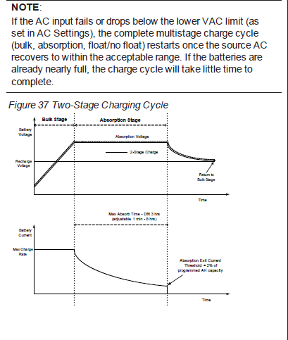
Two-Stage charging
Two-stage (or no float) mode differs from an ordinary three-sage charge mode in that it does not continuously maintain the battery at float voltage. It is sometimes called no-float charging. See "Battery Charging Reference" above for a graph of the two-stage charging profile.
The charging voltage delivered to the battery depends on the battery's:
- Type setting
- Temperature (by switch setting or battery temperature sensor)
- State of charge
The two automatic stage are:
- Bulk
- Absorption

Bulk Stage
Bulk charge is the first stage in the charging process and provides the batteries with a controlled, constant current. Once the battery voltage rises to the absorption voltage threshold, the charger switches to the absorption stage.

Absorption Stage
Absorption charge is the second stage of battery charging and provides the batteries with a controlled, constant voltage. During this stage, the current drawn by the batteries slowly decreases. When this current falls below 2% of the battery capacity, or when the configurable. Absorb Time expires, the charger switches to the Float or NoFloat stage, depending on the selected charge cycle. The timer begins when the battery voltage is above the bulk termination voltage for three minutes.

The Freedom SW transitions to the float stage if either one of the following two conditions are met:
- The charge current allowed by the batteries falls below the exit current threshold, which is equal to 2% of the programmed battery capacity (for a 500 amp-hour battery bank, this would be 10 amps), for three minutes.
- The Freedom SW has been in absorption for the programmed maximum absorption time limit. The default is 8 hours, but the time limit is programmable from 1 minute to 8 hours.
NOTE: If there are DC loads on the batteries, the charger's current may never decrease to a level to initiate the next stage of charging. In this case, the charger would stag in absorption until the Absorb Time setting is reached.
To make sure the charger does not remain in absorption for too long, adjust Absorb Time on the Charger Settings. the timer begins at the start of the absorption stage and terminates absorption charging if the charge current does not decrease to below 2 per cent of the battery capacity before the Absorb Time setting expires. The Absorb Time setting may be increased if the charge cycle continually runs the full Absorb Time in the absence of DC loads. This is an indication of too large a battery bank for the selected Absorb time setting.
Float Stage
Float charge maintains the batteries slightly above the self discharge voltage of the batteries. The charge current in float is the current necessary to maintain the batteries at the Float Voltage setting, limited only by the inverter's capability or other settings that limit the inverter's maximum charge rate. Float charging reduces battery gassing, minimizes watering requirements (for flooded batteries), and makes sure the batteries are in a constant state of readiness. When three-stage charging is selected, the charger automatically switches to the float stage after the batteries have received a bulk and absorption charge (see Figure 37 on page 62). The batteries are maintained at the default float voltage level for the selected battery type or the voltage selected under Float Voltage on the Custom Battery Settings.

Two-Stage Charging Process
Two-stage (or not float) mode differs from an ordinary three-stage charge mode in that it does not continuously maintain the battery at float voltage. Instead, the Freedom SW begins charging the battery in bulk mode whenever the battery voltage drops below the recharge level. While the battery voltage is above the recharge level the inverter's AC transfer switch continues to pass power through from the utility grid to the loads, but does not actively charge the batteries.
Two-stage mode increases efficiency of utility connected system by reducing the amount of power consumed by the inverter and batteries compared to when the battery is continuously maintained at Float Voltage. This feature can extend the life of most batteries.

Equalize Charging


Maintaining the Freedom SW Unit

TROUBLESHOOTING
This section will help you narrow down the source of any problem your encounter.
Before contacting customer service, please work through the steps listed below.
1. Check for a warning or fault message on the RV-C system device controller, if available or a fault code on the inverter information panel. If a message is displayed, record it immediately.
2. As soon as possible, record the conditions at the time the problem occurred so you can provide details when you contact customer service for help. Include the following information;
- What loads the Freedom SW was running or attempting to run.
- What the battery condition was at the time (voltage, etc.) if known
- Recent sequence of events (for example, Charging had just finished, utility grid had failed but the inverter did not come on)
- Any known unusual AC input factors such as low voltage or unstable generator output
- Whether any extreme ambient conditions existed at the time (temperature, vibrations, moisture, etc.)
3. Attempt the solution indicated in these guidelines
4. If your inverter information panel is not displaying a Fault LED, check the following list to make sure that the present state of the installation allows proper operation of the unit.
- Is the inverter/charger located in a clean, dry, adequately ventilated place?
- Are the battery cables adequately sized as recommended in the Installation guide?
- Is the battery in good condition?
- Are the DC connections tight?
- Are the AC input and output connections and wiring in good condition?
- Are the configuration settings correct for your particular installation?
- Are the disconnects and AC breakers closed and operable?
- Have any of the fuses blown in the installation?
Contact customer support for further assistance. Please be prepared to describe details of your system installation to provide the model and serial number of the unit. See the front and/or back of the manual for contact information.
Troubleshooting the Unit
The Freedom SW is designed with a number of protection features to provide efficient operation. If, however, you have any problems operating your inverter/charger read this troubleshooting chapter.
If you cannot resolve the problem, record the information about your system. This information will help your dealer or customer service to assist you better when you contact them.

Detected Fault Types

Detected Warning Types


Inverter Applications
The Freedom SW performs differently depending on the AC loads connected to it. If you are having problems with any of your loads, read this section.
Resistive Loads
Resistive loads are the easiest and most efficient to drive. Voltage and current are in phase, which means they are in step with one another. Resistive loads generate heat in order to accomplish their tasks. Toaster, coffee pots, and incandescent lights are typical resistive loads. It is usually impractical to run larger resistive loads-such as electric stoves and water heaters-from an inverter due to their high current requirements. Even though the inverter may be able to accommodate the load, the size of battery bank will limit inverter run time.
Motor Loads
Induction motors (AC motors without brushes) require up to six times their running current on startup. The most demanding are those that start under load (for example, compressors and pumps). Of the capacitor start motors (typical in drill presses and brand saws, for example), the largest you can expect to run is one horsepower. Universal motors are generally easier to start. Check that the Locked Rotor Amps (LRA) rating of the motor load does not exceed the maximum surge current rating of the inverter. Since motor characteristics vary, only testing will determine whether a specific load can be started and how long it can be run.
If a motor fails to start within a few seconds or loses power after running for a time, it should be turned off. When the inverter attempts to start a load that is greater than it can handle, the inverter may shut down from an AC overload fault.
Problem Loads
Very Small Loads
If the power consumed by a device is less than the threshold of the load sense circuitry, and Load Sense is enabled, the inverter will not run. Most likely the solution will be to disable load sense or lower the sense threshold.
Fluorescent Lights and Power Supplies
Some devices cannot be detected when scanned by load sense circuitry. Small fluorescent lights are the most common example. Some computers and sophisticated electronics have power supplies that do not present a load until line voltage is available. When this occurs, each unit waits for the other to begin. To drive these loads, either a small companion load like a light bulb rated for more than the Search Watts setting must be used to bring the inverter out of load sense, or th inverter may e programmed to remain on by disabling load sense. See Using Load Sense on page 49.
Clocks
You may notice that your clocks are not accurate. Some of the clocks on your appliances may reset when the Freedom SW is in load sense.
Searching
When the inverter is in load sense, it may fail to start some loads even though the rated wattage on the load is more than the rated wattage on the load is more than the Search Watts setting. Disable load sense or apply an additional load (companion load) to make the inverter exit load sense.
SPECIFICATIONS


