Lifeline Batteries


NOTICE: The technical data contained herein has been reviewed and approved for general release on the basis that it contains no export controlled information. No part of this document may be copied or reproduced by any means, including electronic or mechanical, without written permission from Concorde Battery Corporation.
DISCLAIMER: The technical data contained herein is based upon the best information available as of the latest revision date. Concorde Battery Corporation makes no warranty of merchantability, fitness for any particular purpose, or any other warranty, expressed or implied, with respect to such information, an we assume no liability resulting from its use. It is the obligation of each user of the product to determine the suitability for any particular application and to comply with the requirements of all applicable laws regarding use and disposal of this product.


SAFETY SUMMARY
DANGER OF EXPLODING BATTERIES
Lead acid batteries can produce explosive mixtures of hydrogen and oxygen. Take the following precautions:
- Never install batteries in an airtight or sealed enclosure and make sure installation is adequately ventilated.
- Charge batteries in accordance with the instructions given in this manual.
- Keep all sparks, flames and cigarettes away from batteries.
- Connect cables tightly to the terminals to avoid sparks.
- Wear proper eye and face protection when installing and servicing batteries.
DANGER OF CHEMICAL BURNS
Lead acid batteries contain sulphuric acid electrolyte which can cause severe burns to body tissue. Take the following precautions:
- Avoid contact of the electrolyte with skin, eyes or clothing.
- Never remove or damage vent valves.
- In the event of an accident, flush with water and call a physician immediately.
DANGER OF BURNS IF TERMINALS ARE SHORTED
Lead acid batteries are capable of delivering high currents if the external terminals are short circuited. The resulting heat can cause severe burns and is a potential fire hazard. take the following precautions:
- Do not place metal objects across battery terminals.
- Remove all metallic items such as belt buckles, watches, bracelets and rings when installing or servicing batteries.
- Wear insulating gloves when installing or servicing batteries.
- Use insulating tools when installing or servicing batteries.
DANGER OF THERMAL RUNAWAY
Thermal runaway is a condition in which the battery temperature increases rapidly resulting in extreme overheating of the battery. Under rare conditions, the battery can melt, catch on fire, or even explode. Thermal runaway can only occur if the battery is at high ambient temperature and/or the charging voltage is set too high. Take the following precautions:
- Charge batteries in accordance with the instructions given in this manual.
- Do no install batteries near heat sources or in direct sunlight that may artificially elevate their temperature.
- Provide adequate air circulation around the batteries to prevent heat build up.


CHAPTER 1 - INTRODUCTION
1.1 Company Background
Concorde Battery Corporation was founded in 1977 and is a manufacturer of premium quality lead acid batteries. Originally, Concorde's main product emphasis was dry charged and gelled electrolyte lead acid batteries. In 1985, Concorde developed its valve regulated, absorbent glass mat (AGM) technology for use in aircraft applications. The success of this technology in the aviation market has been outstanding. Concorde is now the largest manufacturer of valve regulated lead acid batteries for both commercial and military aircraft.
In 1986, Concorde further developed the AGM technology for deep cycle application. This development effort provided higher energy density (higher capacity) and better cycle life than its gelled electrolyte battery. Concorde soon discontinued the gel product line and concentrated all engineering developments on the AGM product line. In 1987, Concorde began supplying the marine and recreational vehicle market with our deep cycle AGM batteries Over the years it has been our design expertise, quality and customer focus that has made Concorde a leader in providing the best battery available for this market segment. Concorde is committed to the proposition that the customer deserves the best performing and highest quality product. Our batteries are tailored to the application rather than make the designer/user settle for what is available. It is this commitment - to meet the needs of the customer - that sets Concorde apart.
1.2 Overview of Lifeline AGM Technology
Lifeline AGM batteries are valve-regulated, recombinant gas, absorbed electrolyte, lead acid batteries. The cells are sealed with a pressure relief valve that prevents gases within the battery from escaping. The positive and negative plates are sandwiched between layers of glass mat consisting of a blend of glass micro fibers of varying length and diameter. This blend features superior wicking characteristics and promotes maximum retention of the electrolyte. An envelope of micro porous polyethylene surrounds each wrap of glass mat to further protect the plates from shorting. Electrolyte is absorbed and held in place by the capillary action between the fluid and the glass mat fibers. The mat is over 90% saturated with the electrolyte. By design it is not totally saturated with electrolyte, a portion is filled with gas. This void space provides the channels by which oxygen travels from the positive to the negative plates during charging. When the oxygen gas reaches the negative plate, it reacts with lead to form lead oxide and water. This reaction at the negative plate suppresses the generation of hydrogen that otherwise would come off the negative plate. In this manner, virtually all of the gas is "recombined" inside the cell, eliminating the need to add water, resulting in "maintenance free" operation. Furthermore, since the acid electrolyte is fully absorbed in the AGM separator, the battery is nonspillable even when turned upside down.
1.3 About this Manual
This manual is intended to provide the customer with technical information for selecting, installing, operating, and servicing Lifeline AGM batteries. The next Chapter provides a detailed description of the product, its design features and materials of construction. Concorde is very proud of this innovative product line and we think you will share our enthusiasm. Chapter 3 provides a comparison of Lifeline with other lead acid technologies: flooded-electrolyte batteries, gelled-electrolyte batteries, and AGM batteries fro other manufacturers. Chapter 4 presents an overview of the battery specifications for the Lifeline product line; detailed specifications for each model are published separately. Chapter 5 provides instructions for storing, operating and servicing Lifeline AGM batteries. Chapter 6 gives important safety information. Further technical information can be found in the Appendices. If you have additional questions beyond what is covered in this manual, please contact Concorde Battery Corporation or any of our distributors.
CHAPTER 2 - BATTERY CONSTRUCTION
2.1 Component Description
Refer to the battery pictorial in Section 2.2 showing a cut away view of the cell and a summary of the features and benefits. A more detailed description of the battery's construction is given below.
GRIDS - The negative grid is made of pure lead calcium allow. The positive grid is extra thick and is made from a proprietary, pure lead-tin-calcium alloy with special grain refiners. These features improve corrosion resistance of the grid and gives the battery excellent cycling capability and float life.
PLATES - The grids are pasted on stat-of-the-art pasting machines to give the highest quality plates with tightly controlled weight and thickness specifications. The lead oxide paste used to make the positive plates is our high density formula. With time and use, the active material tends to soften and give less discharge capacity. The high density paste formula retards the active material softening and extends battery life.
ABSORBENT GLASS MAT (AGM) SEPARATOR - The AGM is a premium blend of glass micro fibers having an optimum ration of fine and extra fine fiber sizes. This blend features superior wicking characteristics and promotes maximum retention of the electrolyte. The AGM layer is squeezed to an optimum level of compression during assembly to provide sufficient contact with the surface of the plate over the life of the battery. This compression also promotes retention of the active material if the battery is ex\posed to shock or vibration conditions.
POLYETHYLENE ENVELOPE - Concorde is the only manufacturer that envelopes the AGM separator with a thin layer of microporous polyethylene. The microporous layer is wrapped around the glass-matted plate and then sealed along the sides to eliminate the possibility of shorts at the edges of the plate (a common failure mode). The microporous polyethylene is more durable and puncture resistant than the AGM material alone and significantly reduces the occurrence of plate of plate shorts.
INTERCELL CONNECTIONS - Massive "over the partition" fusion welds are used which increase the strength of the intercell connection. This minimizes the possibility of open welds and provides a low resistance connection between cells. Other manufacturers use "through the partition" spot welded construction that inserts a weak point into the assembly because of the small cross section area and the difficulty of making a reliable weld and leak proof construction.
HIGH IMPACT, REINFORCED CONTAINER & COVER - The battery container and cover are made of a thick walled polypropylene copolymer. This material provides excellent impact resistance at extreme low temperatures and minimizes bulging at high temperatures.
COVER-TO-CONTAINER SEAL - The batteries use an epoxy-filled tongue and groove seal between the cover and container. Most other manufacturers heat seal their cover to the container. The epoxy-filled tongue and groove seal is a far stronger than a heat seal and will not separate in high or low temperature extreme applications.
PRESSURE RELIEF SAFETY VALVE - Each cell in the battery employs a pressure relief safety valve. The valve is designed to release excess pressure that builds up over time to vent the small quantity of gasses that do not recombine inside of the battery. Once the pressure is some hydrogen, and these gasses rapidly dissipate into the atmosphere.
TERMINALS - Lifeline AGM batteries are available in a variety of terminal configurations. Most terminal types are made of copper alloy which provide a ling lasting, low resistance electrical connection. The copper alloy terminals are non corrosive, unlike lead terminals. Additionally, the copper alloy terminals offer increased environmental protection and personal safety in comparison to commonly used lead terminals. Refer to the pictorial in Section 2.3 to see a detailed view of the various terminal types that are available.
HANDLES - Lifting handles are incorporated into all Lifeline AGM batteries. This provides easier handling for lifting, carrying and installation.


CHAPTER 3 - TECHNOLOGY COMPARISON
3.1 Lifeline versus Flooded Batteries
Flooded-electrolyte lead acid batteries have been around since 1859 and tend to be less expensive than AGM or Gel batteries. However, they have major deficiencies compared to AGM or Gel batteries. For instance, deep cycle flooded lead acid batteries contain antimony in the grid alloy which causes a high rate of self discharge and rapid water loss due to gassing reactions. The escape of hydrogen and oxygen from the battery represents a serious safety hazard if the gasses are not ventilated properly. In flooded batteries, replacing the antimony lead alloy with calcium lead alloy reduces the amount of gassing the water loss, but the cycle life is much lower and they are no longer considered deep cycle batteries.
Electrolyte stratification can occur in all types of flooded batteries. As the battery is discharged and charged, the concentration of acid becomes higher at the bottom of the cell and becomes lower at the top of the cell. The low acid concentration reduces capacity at the top of the plates, and the high acid concentration accelerates corrosion at the bottom of the plates and shortens the battery life. Although stratification can be minimized by raising the charging voltage so that the increased gassing agitates the electrolyte, this will accelerate the water loss and watering frequency.
One other difference is that flooded batteries can not tolerate freezing temperatures when in the discharged state, whereas AGM batteries are not damaged by freezing temperatures. The following table provides a side by side comparison of Lifeline AGM and flooded deep cycle batteries.

3.2 Lifeline versus Gel Batteries
Gel batteries have been commercially available since the early 1970's and are still offered by some manufacturers. Concorde manufactured gel batteries for many years before developing the AGM technology and, therefore, is aware of inherent deficiencies associated with gel batteries.
The gel product employs a highly viscous, semisolid mixture of silica gel and dilute sulfuric acid in a colloidal suspension as an electrolyte. The electrolyte is difficult to keep homogeneous and the solid silica can separate from the acid, creating a "flooded" battery. Handling and vibration exposure and operational factors that can cause the silica and acid mixture to separate as there is no chemical bond. In hight temperature environments, the semisolid electrolyte develops cracks and voids the reduce contact between the plates and causes the battery to lose capacity. This same effect gradually occurs even at normal room temperatures.
By contrast, AGM batteries employ a glass micro fiber mat separator that holds the liquid electrolyte like a sponge. Shrinkage of the separator does not occur as the battery ages and the electrolyte remains in direct contact with the plates. The electrolyte remains immobilized even when the battery is exposed to severe vibration, so electrolyte spillage or leakage is prevented.
Since it is easier to fill a container with a liquid than a semi-solid, AGM batteries require less space between battery plates. The closer plate spacing gives the AGM battery a lower internal resistance, making it more charge efficient and giving better power performance on discharge, especially at low temperatures.
Gel batteries are also more sensitive to charging voltage. If the charging voltage is not controlled within a very tight range relative to the battery's temperature, the life of the battery will be adversely affected. For example, one manufacturer of gel batteries claims that if the charging voltage is 0.7V higher than the recommended level, the cycle life will be reduced by 60 percent. The reason for this effect is the limited oxygen recombination capability of gelled batteries. Lifeline AGM batteries are more forgiving in overcharge conditions and their ability to recombine the hydrogen and oxygen gases back into water is more efficient. With Lifeline AGM batteries, tests have shown that increasing the charging voltage 1.0V above the recommended charging voltage results in only a 23% reduction in the cycle life.
The charge acceptance of gel batteries is also less than that of Lifeline AGM batteries. This means it takes longer to recharge gel batteries. As an example, tests have shown that when discharged to 50% of related capacity (fairly common in a deep cycle applications), gel batteries took twice as long to reach full charge as compared to Lifeline AGM batteries.
The following table provides a side by side comparison of Lifeline AGM and gel batteries:

3.3 Lifeline versus other AGM Batteries
Lifeline AGM batteries have been specifically designed for true deep cycle, long service life capability in adverse temperature and handling conditions. Concorde uses extra thick positive plates, high density paste, thick AGM separator layers encased within a microporous polyethylene envelope, thick walled containers with epoxy-sealed covers. A side by side comparison of Lifeline AGM batteries with typical AGM batteries from other manufacturers is provided in the following table:

CHAPTER 4 - BATTERY SPECIFICATIONS
4.1 Battery Models
The Lifeline Series consists of deep cycle as well as engine starting batteries. Capacities of the dep cycle batteries range from 33 to 1200 ampere hours (rated at the 20 hour rate) and a variety of 2-volt, 6-volt and 12-volt models are available. Ratings of the starting batteries range from 550 amperes to 810 amperes (CCA at 0ºF) and these are only available in 12 volt models. Refer to the battery specification sheet (published separately) for a complete listing of the mechanical and electrical specifications for each battery mode.
4.2 Terminals
Standard Terminals: The following table shows the standard type of terminal used on each battery model:

Optional Terminals: The 2 and 6 volt models are available with marine terminals on a special order basis.
Terminal Hardware: When requested, batteries are supplied with silicon bronze bolts, nuts and washers as required for installation.
Terminal Torque Values; Use 35 in-lbs/4.0 nm for M6. Use 70 in-lbs/7.9 nm for M8 and M10.
4.3 Handles
All batteries include lifting handles, either built into the cover, dual ropes attached to the cover, or a single plastic handle attached to brackets on the sides of the container.
4.4 Definition of Ratings
Capacity ratings are after 15 cycles per BCI specifications and are stated at 77ºF (25ºC) to 1.75 volts per cell.
4.5 Temperature Range
Storage (when fully charged): -67ºF (-55ºC) to 122ºF (50ºC)
Operating: -40ºF (-40ºC) to 160ºF (71ºC
4.6 UL Recognition
All Lifeline AGM batteries meet the requirements of UL 1989 (Standby Battery) and are UL recognized under UL File Number MH-17983.
4.7 Shipping Classification
Lifeline AGM batteries have been tested and determined to be in compliance with the vibration and pressure differential tests in accordance with DOT 49 CFR 173.159(d) and Special Provision A67 of the International Air Transport Association (IATA) Dangerous Goods regulations. As such, they are classified as a "NONSPILLABLE BATTERY" and can be shipped as non-hazardous material by any means. To comply with DOT shipping regulations, the battery must be packaged to protect against short circuits and the battery and outer packaging must be plainly and durably marked "NONSPILLABLE" or "NONSPILLABLE BATTERY".
CHAPTER 5 - COMMISSIONING AND SERVICING INSTRUCTIONS
5.1 Storage
Lifeline Batteries are charged at the factory and are ready for installation when they are received. Batteries may be stored prior to installation for up to 2 years, provided they are boost charged as described below. Batteries should be stored in the coolest environment available, preferably not exceeding 68ºF (20ºC). The higher the temperature, the faster the battery will self-discharge and require boost charging. See Appendix C for data on storage time versus temperature.
While in storage, batteries should be boost charged every 90 days or when the open circuit voltage (OCV) drops to 12.5 volts for a 12 volt battery (6.25 volts for a 6 volt battery and 2.08 volts for a 2V battery). This OCV corresponds to approximately 75% state of charge. Boost charge batteries using a constant voltage charger set at 14.4 to 15.0 volts for a 12 volt battery (7.2 to 7.5 volts for a 6 volt battery and 2.40 to 2.50 for a 2 volt battery). The boost charge should be applied until the charging current falls below 0.5 percent of the battery's 20 hour rated capacity (0.5 amps for a 100 AH battery).
5.2 Installation
Be sure there is adequate ventilation in the area where the batteries are to be installed (see Chapter 6). Batteries may be installed in any orientation except upside down (i.e., terminals facing the earth). The space surrounding adjacent batteries should be at least 0.25 inch to permit airflow around each battery. Always use batteries of the same size and condition in multi-battery installations. When replacing batteries, it is best to replace the entire set of batteries so they remain balanced.
Connect batteries using cabling that is sized for the maximum load of the system. The voltage drop on the cables during charging should not exceed 0.2 volts at full output. Protect the battery terminals from shorting during installation.
Batteries may be connected in series (voltage adds, capacity stays the same), in parallel (capacity adds, voltage stays the same), or a combination of series and parallel (voltage and capacity adds). Each of these connections options are illustrated in Figures 5-1 through 5-3, respectively.

Connection options for 4-terminal batteries are illustrated in Figures 5-4 through 5-8. For low rate applications (current levels less than 400 amperes), only two of the four terminals need to be connected, but it is still best to use all four terminals fo redundancy. For high rate applications (current levels greater than 400 amperes), all four terminals should be connected.


5.3 Discharging
Discharge data for Lifeline AGM batteries are given in Appendix C. The capacity delivered by the battery depends on the rate of discharge as well as the battery temperature. The battery will deliver less capacity as the discharge rate increases and less capacity as the temperature is lowered. Graphs are provided in Appendix C to quantify these effects. Peukert plots (Amps vs Time) are also included, along with formulas for calculating the current that can be removed or any discharge time from 0.5 hours to 120 hours. To calculate the discharge time for a specified amperage, these formulas can be inverted as follows:

In general, batteries should be sized such that the rated capacity is at least twice the capacity required by the load. For example, if 100 Ah is required on average, select at least a 200Ah battery. This approach will limit the average depth of discharge to 50% and will dramatically extend the life of the battery (see chart of Cycle Life versus Depth of Discharge in Appendix C).
5.4 Charging
Charging Lifeline AGM batteries is a matter of replacing the energy removed during discharge plus a little extra to make up for charging inefficiency. The amount of energy necessary for complete recharge depends on the depth of discharge, rate of recharge, and temperature. Typically, between 102% and 110% of the discharged ampere-hours must be returned to full recharge.
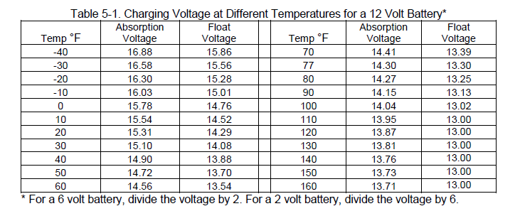
The most efficient method of charging Lifeline AGM batteries is to use a 3 stage charging profile. In the first stage, a constant current is applied until the voltage reaches a pre-set limit. The first stage is often called the Bulk charging stage. In the second stage, the voltage is held constant at the same pre-set limit until the charging current tapers to a very low value, at which point the battery is fully charged. The second stage is often call the Absorption charging stage. A voltage limit of 14.3 volts plus or minus 0.05 volt for a 6 volt battery) should be used when the battery temperature is 77ºF (25ºC). The battery is fully charged when the current drops below 0.5% of the battery's rated capacity (0.5A for a 100Ah battery). In the third stage, the charging voltage is reduced to a lower value that minimizes the amount of overcharge, while maintaining the battery at 100% state of charge. This third stage is often called the Float charging stage. A float voltage of 13.3 plus or minus 0.1 volts (6.65 plus or minus 0.05 volts for a 6 volt battery) should be used when the battery temperature is 77ºF (25ºC). The charging voltages at other temperatures can be determined from the following table:
The charging current during the Bulk stage should be set as high as practical; higher current levels mean faster recharge time. Due to the low impedance design, Lifeline batteries can tolerate in-rush current levels as high as 5C (500A for a 100Ah battery). The time to reach full charge at temperatures in the range of 68 to 86ºF (20-30ºC) can be estimated from the following equation:
Note that the above formula is approximate and the full charge state should be verified using the criteria given above (current drops below 0.5% of rated capacity). If the recharge does not return 102% to 110% of the discharged capacity, the battery's state of charge will gradually "walk down" as it is cycled leading to premature failure. Therefore, it is important to verify that the battery is not being undercharged.
For repetitive deep cycling applications (deeper than 50% DOD), chargers should have an output current of at least 0.2C (20 Amps for a 100 Ah battery). If the output current is less than this value, the cycle life of the battery may be negatively affected. If a charger with at least 0.2C output is not practical, and alternative charge profile using a low rate constant current stage at the end of the absorption stage will normally improve the cycle life. The constant current stage should be at 0.02C (2 Amps for a 100 Ah battery) for no more than one hour.
Some types of battery chargers allow the user to input the Peukert constant to obtain an optimum charging profile. For Lifeline batteries, the recommended value of the Peukert constant is n=1.12.
5.5 Conditioning
Conditioning should only be done when the battery is showing symptoms of capacity loss due to extended time in a partial or low state of charge condition. This could be caused, for example, by low charging voltage for an extended number or charge cycles, or by repeatedly charging to only 90% state of charge.
NOTE: Some chargers use the term Equalizing Charge instead of Conditioning Charge. An Equalizing Charge is generally applied to flooded lead acid batteries that are susceptible to acid stratification. However, an Equalizing Charge may be used to provide a Conditioning Charge for Lifeline batteries as described below.
To apply a conditioning charge, first go through the normal charge cycle to bring the battery to full charge. The conditioning charge should then be applied by charging for 8 hours. At 77ºF (25ºC), the conditioning voltage should be set at 2.58 VPC (15.5 volts for a 12 volt battery). The conditioning voltage at other temperatures is shown in Table 5-2. By using the temperature-compensated conditioning voltage, batteries that are not in controlled temperature environments may be conditioned without bringing them to room temperature. If temperature compensation is not available, it is best to bring the battery as close to room temperature as possible before applying the conditioning charge.

5.6 Deep Discharge Recovery
Batteries that have been in storage for long periods of time without boost charging, or have been kept deeply discharged for an extended time, may need to be charged at constant current instead of constant voltage to restore capacity. The following procedure is effective if the batteries are not too badly sulfated.

5.7 Capacity Testing

5.8 Temperature Considerations
The temperature of the battery has a significant impact on its performance and life capability. Battery capacity is reduced significantly in cold temperatures. For example, a battery that operates continuously at -18ºC (0ºF) will only provide about 60% of its normal room temperate capacity. Appendix C provides a chart of capacity versus temperature at various discharge rates.
Battery life is also affected by temperature. As a rule of thumb, the battery life decreases by 50% for every 10ºC rise in temperature. Thus, a battery that lasts 6 years at 25ºC will last 3 years at 35ºC, 1.5 years at 45ºC, and 0.75 years at 55ºC.
It should be realized that the temperature of the battery itself and ambient temperature can be vastly different. While ambient temperatures can change very quickly, battery temperature change is much slower. This is due to the large thermal mass of the battery. It takes time for the battery to absorb temperature and it takes time for the battery to relinquish temperature.
If the battery is exposed to cold climates, the state of charge should be kept at a maximum to prevent freezing of the electrolyte. A fully charged battery will not freeze even under the coldest weather conditions, but a discharged battery will freeze even when moderately cold. Table 6-2 gives the freezing point of electrolyte at various states of charge.
Frozen batteries are not capable of charging or discharging except at very low rates, and may be permanently damaged by expansion of the electrolyte. If a battery becomes frozen, it should be thawed by placing it at room temperature for at least 24 hours, and then charged in accordance with Sections 5.4, 5.5 or 5.6 as applicable. However, if the battery container has any evidence of cracking, the battery is no longer serviceable and should not be used.

5.9 Servicing
Lifeline AGM batteries do not need electrolyte additions as do flooded lead-acid batteries, but periodic servicing is essential to assure continued integrity of the battery system. Servicing should include good record keeping to document the life history of the battery system and to identify whether corrective action needs to be taken.
The following servicing schedule is recommended:


5.10 Recycling
Batteries that have reached the end of their service life should be returned to a local or regional collection center for recycling. All local regulations are ordinances must be followed. Never discard Lifeline AGM batteries in the trash or in a landfill. The recycle rate of lead acid batteries is close to 100% and this is very good for the environment!
CHAPTER 6 - SAFETY INFORMATION
There are four main safety hazards associate with the use of any valve regulated lead acid (VRLA) battery. These hazards are a) Release of ignitable gas, b) Exposure to acid, c) Shorting of terminals, d) Thermal runaway. This chapter provides a description of each of these hazards and means to mitigate them.
6.1 Release of Ignitable Gasses

6.2 Exposure to Acid

6.3 Shorting of Terminals

6.4 Thermal Runaway

APPENDIX A - GLOSSARY OF BATTERY TERMS
AGM - Stands for Absorbed Glass Mat. This is the separator system used in all Lifeline AGM batteries.
Active Material - Electrode material which produces electricity during its chemical conversion. In the positive plate it is lead dioxide. In the negative plate, it is sponge lead.
Ampere - Unit of electrical current abbreviated as amps or A. Amps = Watts/Volts or A = W/V.
Ampere Hour (Ah) - The capacity of a storage battery is measured in ampere hours. One ampere hour is defined as a current flow of one ampere for a period of one hour. Five ampere hours means a current flow of one ampere for five hours, a current flow of 2 1/2 ampere for 2 hours, or any multiply of current and time that will result in five. This relationship can be expressed as follows: Capacity (Ampere hours)=I*T, where I is the current (in amperes) and T is the time (in hours). The capacity of a storage battery is based on a given discharge rate, since the capacity will vary with the rate of discharge.
Boost Charge - A charge applied to a battery which is already near a state of full charge, usually of short duration.
Capacity - The quantity of electricity delivered by a battery under specified conditions, usually expressed in ampere hours.
Capacity, Rated - A designation by the battery manufacturer which defines the performance of a new battery at a defined rate of discharge. For Lifeline AGM batteries, the rated capacity is based on the 20 hour rate.
Capacity, Residual - Capacity, remaining at particular point in time and set of operating conditions, usually at a partial state of charge condition.
Cell Reversal - Reversing of polarity within a cell in a multi cell battery due to over discharge.
Charge - The conversion of electrical energy from an external source, into chemical energy within a cell or battery.
Charge Rate - The rate at which current is applied to a cell or battery to restore its capacity.
Charge Retention - The ability of a charged cell or battery to resist self discharge.
Charge, State of - Ratio of the amount of capacity remaining in a battery to the capacity when fully charged. A battery at 25% state of charge has 25% capacity remaining versus what it could give if fully charged.
Charger - Device capable of supplying electrical energy to charge a battery.
Charging - The process of converting electrical energy to stored chemical energy. The opposite of discharging.
Charging Efficiency - Ratio of the Ampere hours delivered on discharge to the Ampere hours needed to fully charge a battery.
Conditioning - A special constant current charge process used to restore a battery's capacity after extended storage periods or deep discharge exposure. Also known as reconditioning.
Constant Current (CC) Charge - Charging technique where the output current of the charge source is held constant. Warning! This procedure may damage the battery if performed on a repetitive basis.
Constant Voltage (CV) Charge - Charging technique where the output voltage of the charge source is held constant and the current is limited only by the resistance of the battery and / or the capacity of the charge source. Also known as Constant Potential (CP) charge.
Current - The rate of flow of electricity. The movement of electrons along a conductor. It is comparable to the flow of a stream of water. The unit of measurement is an ampere.
Cut Off Voltage - Battery voltage reached at the termination of discharge. Also known as end point voltage or EPV.
Cycle - One sequence of discharge and charge.
Cycle Life - The total number of charge/discharge cycles before the battery reaches end of life (generally 80% of rated capacity).
Deep Discharge - Withdrawal of more than 80% of the rated capacity.
Depth of Discharge - The portion of the capacity taken out during discharge, expressed as a percent of rated capacity.
Discharge - The conversion of the chemical energy of a cell or battery into electrical energy and withdrawal of the electrical energy into a load.
End of Life - The stage at which the battery fails to deliver acceptable capacity (typical 80% of nameplate rating).
Float charge - A method of maintaining a battery in a charged condition by continuous, long term, constant voltage charging at level sufficient to balance self-discharge.
Gassing - The evolution of gas from one or more of the electrode plates in a cell. Gassing commonly results from local actions (self discharge) or from the electrolysis of water in the electrolyte during charging.
Internal Impedance - Same as Internal Resistance.
Internal Resistance - The opposition or resistance to the flow of a direct electric current within a cell or battery; the sum of the ionic and electronic resistance of the cell components. Its value varies with the current, state of charge, temperature, and age. With an extremely heavy load, such as an engine starter, the cell voltage may drop significantly. This voltage drop is due to the internal resistance of the cell. A cell that is partly discharged has a higher internal resistance than a fully charged cell, hence it will have a greater voltage drop under the same load. This change is internal resistance is due to the accumulation of lead sulfate in the plates.
Open Circuit Voltage - The voltage of a battery when it is not delivering or receiving power, and has been at rest long enough to reach a steady state (normally, at least 4 hours).
Overcharge - The forcing of current through a cell after all the active material has been converted to the charged state. In other words, charging continued after 100% state of charge is achieved. The result will be the decomposition of water in the electrolyte into hydrogen and oxygen gas, heat generation, and corrosion of the positive electrode.
Self Discharge - The decrease in the state of charge of a cell or a battery, over a period of time, due to internal electrochemical losses.
Series Connection - Voltage of the system is cumulative. Capacity stays the same.
Shelf Life - The period of time (measured from date of manufacture) at a specified storage temperature after which the cell or battery needs to be boost charged so it does not suffer permanent capacity loss.
State of Charge (SOC) - The available ampere hours in a battery when fully charged relative to its rated capacity.
Sulfation - Refers to the formation of hard lead sulfate crystals in the plates that are difficult, if not impossible, to reconvert to active material.
Temperature, Ambient - The average temperature of the battery's surroundings.
Temperature, Cell - The average temperature of the battery's internal components.
Trickle Charging - Method of charging in which the battery is either continuously or intermittently connected to a constant current charging source to maintain the battery in a full charged condition. Not recommended for use with Lifeline AGM batteries.
Vent Valve - A normally closed check valve located in a cell which allows the controlled escape of gases when the internal pressure exceeds its rated value.
Venting - A release of gas either controlled (through a vent) or accidental from a battery cell.
APPENDIX B - FREQUENTLY ASKED QUESTIONS (FAQ'S)

APPENDIX C - CHARTS AND GRAPHS


