Koni Shock Absorbers
Access a printable PDF copy at this link: Koni Shock Absorbers.pdf


It is highly recommended that this kit be installed by a KONI
dealer or professional mechanic
Before installation, check all hardware contents. Please contact KONI dealer if any are missing.
Removal and replacement of these suspension components require the vehicle to be lifted off the ground. Ensure correct support is used to prevent any personal injury and damage to the vehicle.
Refer to service manual for any parts that need to be replaced when removed.
Check all suspension components move freely on full
compression and extension.
After height adjustment, use caution and do not over tighten set screw. Over tightening will damage threaded body.
Do not use impact tools on upper strut or shock mount nuts!
Once tis kit is installed, check all suspension components move freely on full compression and extension.
For safety, check all clearances with aftermarket/oversized wheel and tire combinations.
Lowered ride height means reduced angle of slope. Drive with care over ramps, speed humps, etc. once the vehicle has been lowered.

The images used in these instructions are for correct guidance for installation. They may vary from the original product.
Please note that there may be excess oil on the product from assembly. Wipe off with a cloth. This will not damage the product in any way. It may however leave marks on the packaging.
www.koni.com
INFORMATION
Removal and replacement of these suspension components require the vehicle to be lifted off the ground. Ensure correct support is used to prevent any personal injury and damage to the vehicle.
Refer to vehicle’s service manual for specific procedures and
important information.
All suspension bolts with rubber bushings need to be tightened and torqued at ride height when resting on wheels.
After installation headlight adjustment may be necessary.
After installation or height adjustment, wheel alignment is
required.
Before the vehicle is driven, make sure initial setup and heights are as per KONI recommendations.

FRONT AXLE

Refer to service manual for any parts that need to be replaced when removed.

After installation headlight adjustment may be necessary.
After installation or height adjustment, wheel alignment is required.
Before the vehicle is driven, make sure initial setup and heights are as per KONI recommendations.
REMOVAL OF FRONT STRUT
1. Jack up vehicle and install jack stands

2. Remove front wheels
3. Remove the stabilizer linkage (A) from control arm (B).
4. Carefully remove ABS cable and brake line from upper arm (C).
5. Loosen nut (D) and remove bolt (E).
6. Loosen and remove upper shock nuts (F).
7. Loosen and remove bolts (G) and disconnect upper arm from chassis to allow movement in shock absorber (H).
8. Remove shock absorber (H).

INSTALLATION OF GTS FRONT STRUT
1. Install assembled KONI damper (A) into position.
2. Initially hand tighten upper attachments (B).
 Do not torque!
3. Connect upper control arm (C) to chassis and install bolts (D)
 Do not torque!
4. Connect bottom of shock absorber (A) to lower arm (G).
5. Install bolt (E) and fasten nut (F).
6. Torque all bolts to manufacturer specification
 Only use hand tools. Do not use impact tools!
 Refer to vehicle service manual
7. Reconnect ABS line and brake line to control arm (C)
8. Reconnect stabilizer linkage (H) to torque nut (J).
ADJUSTING FRONT RIDE HEIGHT
Before adjusting front ride height, the vehicle must be lifted with wheel hanging to release load on suspension

- There should always be preload on the installed spring assembly

REAR AXLE

- Refer to service manual for any parts that need to be replaced when removed.

After installation headlight adjustment may be necessary.
After installation or height adjustment, wheel alignment is required.
Before the vehicle is driven, make sure initial setup and heights are as per KONI
recommendations.
REMOVAL OF REAR SHOCK AND SPRING
1. Jack up vehicle and install jack stands.
 Make sure vehicle is secured.
2. Remove rear wheels.
3. Loosen and remove stabilizer bar end link nut (A)
4. Loosen nut (B) and remove bolt (C) from the bottom of the shock absorber.
5. Loosen and remove upper shock nuts (D).
6. Remove shock absorber (E)
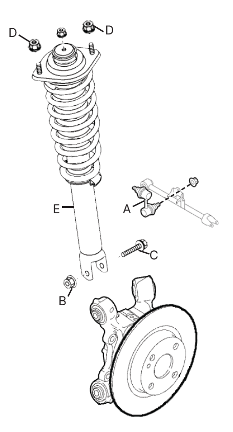
INSTALLATION OF GTS REAR SHOCK AND SPRING
1. Install KONI shock absorber (A).
2. Fasten shock absorber upper mount bolts (B).
3. Connect bottom of shock absorber to hub (E) and install shock absorber lower mount bolt (C).
4. Fasten shock absorber lower nut (D) and tighten.
5. Reconnect and tighten up stabilizer link nut (F)
6. Torque all bolts to manufacturer specification
 Do not use impact tools!
 Refer to vehicle service manual
ADJUSTING REAR RIDE HEIGHT
In order to adjust the rear ride height:
1. Remove the rear spring and adjuster.
2. Untighten the set screw
3. Adjust to desired height
4. Tighten set screw
 Do not over tighten set screw
5. Reinstall rear spring and adjuster
WARNING
There should always be preload on the installed spring assembly

KONI RECOMMENDED ADJUSTMENT RANGE

HOW TO MEASURE RIDE HEIGHT ADJUSTMENT

KONI BUMP PLATES
WARNING
The KONI recommended height adjustment range of this kit has been clearly defined in this
instruction manual. As a safety precaution and for protection of the dampers, additional bump
plates have been clipped onto the piston rod (see figure 1). If the set spring seat height is
within the KONI defined range, bump plates can be removed one by one.
There should always be a minimum of one bump plate installed on each shock absorber (see figure 2)
