Denso Service Manual
Access a printable PDF copy at this link: DENSO_RV_HVAC_Service Manual_0427.pdf

FOREWORD
This manual was developed to assist certified technicians in servicing the air conditioning system on
class A motorhomes built on Ford, GM, Spartan, or Freightliner chassis, equipped with a DENSO air
conditioning system.
Since the dash A/C system utilizes chassis components (compressor, condenser, receiver/drier and
discharge hose), it is advised that the appropriate chassis repair manual for Ford, GM, or Freightliner be
consulted when required or necessary.


GENERAL INFORMATION
1. The Purpose of Air Conditioning
The purpose of an automotive air conditioner is to
maintain a cool, comfortable environment for
passengers.
Here are the four ways this is achieved:
• Temperature Control
• Air Circulation Control
• Humidity Control
• Air Purification

2. Technical Terms
A. Heat
1) Heat Quantity
Heat is a form of energy. There are two
units to measure heat quantity, Kcal or
BTU (British Thermal Unit).
• One Kcal heat quantity changes
the temperature of one Kg of liquid
water by one degree centigrade.
• One BTU of heat changes the
temperature of one pound of liquid
water by one degree Fahrenheit.
1 Kcal = 0.252 BTU
1 BTU = 3.968 Kcal

2) Specific Heat
Specific heat is the quantity of heat
required to CHANGE THE TEMPERATURE
of an object by one degree.
The unit of specific heat is Kcal/kg°C
or BTU/lb°F.

3) Heat Transfer
As heat travels over a distance, it
tends to lose energy. Heat can be
transmitted through CONDUCTION,
CONVECTION or RADIATION. It can
also be transmitted by a combination
of any or all of these methods.
a) Conduction is the transfer of heat by
direct contact. When you heat one
side of a steel bar, the other side
becomes warmer by conduction.
b) Radiation is the transfer of heat by
rays. Heat from the sun is transferred
to the earth in rays. But the
sun isn’t the only object that
radiates heat. Every object that
contains heat can radiate it.
c) Convection is the transfer of heat
by the movement of heated liquid
or gas. When heat is applied to the
bottom of a container of liquid or
gas, the warmed particles at the
bottom expand and rise. The
colder particles at the top, which
are denser than the heated particles,
sink to the bottom.

B. Temperature
1) Temperature Scales
Temperature is the degree to which an
object is hot or cold. The unit generally
used to express this is degrees
Centigrade (°C) or degrees Fahrenheit
(°F). In the Centigrade scale, the
freezing point (solid point) of pure
water is taken as 0°C, and the distance
between the freezing point and
the boiling point are divided into 100
parts and each part is designated as
1°C.
In the Fahrenheit scale, the freezing
point of pure water is taken as 32°F,
and the distance between the freezing
point and the boiling point are divided
into 180 parts with each part designated
as 1°F.
[°C] = 5/9([°F] - 32)
[°F] = 9/5([°C] + 32)

2) Wet Bulb and Dry Bulb Thermometers
The bulb (heat sensitizing part) of a
glass tube thermometer is wrapped
with a gauze or other rough mesh
cloth. One end of the cloth is immersed
in a water container to allow
the water to be drawn up by a capillary
action and to moisten the heat
sensitizing part. The water in the cloth
surface near the heat sensitizing part
evaporates and robs the latent heat of
evaporation from the surrounding air,
causing the air temperature around the
heat sensitizing parts to drop. The
temperature registered by the thermometer
at this time is called the wet
bulb temperature.
This is used to find out the humidity
in combination with the dry bulb
temperature.

3)Dew Point Temperature
When the air surrounding us is cooled,
the air temperature drops, and when
the humidity becomes 100%, that is,
when the dry bulb and wet bulb
temperatures become the same, the
water vapor contained in the air will be
in a saturated state.
On further cooling, the water vapor
reaches a condition where it cannot
remain in a vapor state so that a part
condenses and becomes dew. The
temperature at which the humidity
becomes 100% and dew is formed is
called the dew point temperature.
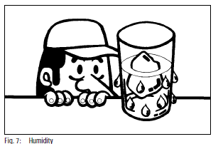
C. Humidity
1) Humidity
When you pour water and ice into a
glass, you notice that drops of water
are generated on the glass. Do you
sometimes wonder where these drops
of water come from?
Drops of water come from the surrounding
air, so humidity is water
vapor contained in the air.
2) Relative Humidity
There are two ways to measure
humidity: relative humidity and absolute
humidity.
The most common way to measure
humidity is using the relative method.
Relative humidity is the amount of
water the air contains, compared with
the amount the air could hold at a
given temperature.
In other words, if the relative humidity
is 50 percent, the air could hold as
much water again as it does at that
temperature.
Water capacity means the amount of
water vapor which the air could hold
at a given temperature. The water
capacity changes according to the
temperature of the air. The water
capacity of cooled air is lower. Therefore,
the amount of vapor in the air at
50°C, 50 percent, is different from that
in the air at 10°C, 50 percent.

3) Absolute Humidity
Absolute humidity is the amount of
water the air contains, compared with
the dry air.
D. Pressure
1) What is Pressure?
Pressure is defined as the vertical
force exerted on a unit area by a solid,
liquid, or gas. The unit generally used
to indicate the pressure is “kg/cm”.
When indicating blower performance,
mmAq (water column) is generally
used, and when indicating pressure
below atmospheric (vacuum), cmHg
(mercury column) is commonly used.
When expressing boiler pressure, the
atmospheric pressure is taken as the
basis, and the pressure is expressed in
number of atmospheres (atmos). The
concept held toward pressure is entirely
in accordance with Pascal’s law.
Pascal’s Law: “Pressure exerted on a
liquid confined in a container is
transmitted undiminished in all directions.
Regardless of container shape,
if the interior area is equal, the pressure
subject there will be equal.”

2) Atmospheric Pressure
This is the pressure that is subjected
on all objects and matter on earth.
This pressure is the weight of the air
surrounding everyone and is equal to
1 atmosphere.
At this pressure the mercury column
will be 760 mmHg (76 cmHg).
1 atm=1.03 kg/cm2=760 mmHg=14.7 psi
Pressure gauges commonly indicate
atmospheric pressure in units of kg/
cm2 or psi.

3) Absolute Pressure
Absolute pressure is that in which a
perfect vacuum is taken as 0 kg/cm2.
Thus, the atmospheric pressure, when
expressed in terms of absolute pressure,
will be 1.03 kg/cm2.
To differentiate, pressure measured
with a gauge is called gauge pressure.
For identification, absolute pressure is
indicated by [kg/cm2 abs.] and gauge
pressure by [kg/cm2G]. Absolute
pressure to gauge pressure relationship
is as follows:
Absolute press. [kg/cm2 abs.] + Gauge
press. [kg/cm2G] + 1.03 kg/cm2
4) Vacuum
Vacuum is the pressure below atmospheric
pressure and is expressed in
terms of a mercury column (cmHg,
mmHg).
When the vacuum is measured with a
mercury column, the difference
between this measurement and that
for atmospheric pressure becomes the
amount of vacuum.
3. Change of State
A. State Change of Water
Now, we will consider how ice changes its
state when we add heat to it, because
water is the most common example to
understand heat and states of object.
If we add heat to ice until the temperature
of ice reaches 0°C (32°F), ice melts into
water, and while the ice is melting, the
temperature of ice and water remains at
0°C. After the ice has melted, the temperature
of water begins to rise.
When the temperature of water reaches
100°C (212°F), water begins to become
steam. Until all the water becomes steam,
the temperature of water remains 100°C
(212°F).

B. Sensible Heat and Latent Heat
The chart below shows the relation
between heat and temperature. There are
two kinds of heat called sensible heat and
latent heat.
Sensible Heat can change the temperature
of water but cannot change the state of
water. Therefore, the sensible heat raises
or lowers the temperature of water. In the
case of water, 1 kg of water at 0°C must
absorb 100 Kcal of sensible heat to
change to 1 kg of water at 100°C.
Latent Heat can change the state of water,
but cannot change the temperature of
water. Ice melts into water by adding
latent heat and water evaporates into
steam by adding latent heat. In the case of
water, 1 kg of ice at 0°C must absorb 80 Kcal of latent heat to change to 1 kg of
water at 0°, and 1 kg of water at 100°C
must absorb 539 Kcal of latent heat to
change to 1 kg of steam.

C. The Three States of Matter
As you know, matter exists in three states:
solid, liquid and gas. In the case of water,
the solid state is ice, the liquid state is
water, and the gas state is steam.

1) Fusion
When a solid melts into a liquid, heat
is absorbed from its surroundings.
2) Solidification
In the opposite situation, when liquid
changes into a solid, heat is released
to its surroundings.
3) Evaporation
When liquid evaporates into gas, heat
is absorbed from its surroundings.
4. The Relationship Between Pressure and Temperature
So far we have been discussing the state of
change that occurs in water under atmospheric
pressure. The boiling point of water or
any liquid changes depending on the pressure
working on the liquid.
Rule 1. When the pressure is high, the boiling
point of liquid also becomes high.
Rule 2. Conversely, under a low pressure,
liquid begins to boil at a lower temperature.
The illustration below shows how the boiling
point is influenced by pressure change.
A. Under normal atmospheric pressure (0 kg/
cm2G) water boils at 100°C.
B. If the pressure exerted on water increases
by 0.09 kg/cm2 from atmospheric pressure,
the water does not boil until water
temperature reaches 118°C.
C. The water under pressure which is lower
than normal atmosphere by 0.4 kg/cm2
begins to boil as soon as the water
temperature passes 84°C.
The above rules between pressure and boiling
point can be applied to all liquids. HFC-134a,
the refrigerant used in automobile air conditioner
is no exception.

5. Basic Theory of Cooling
We feel a little cold even on a hot day after
swimming. This is because water on your
body takes away the heat through evaporation.
The same principle is at work when we
apply alcohol to our arms. Evaporation of the
alcohol removes the heat.
This natural phenomenon can be used to
create coolness. That is, liquid takes the heat
from substances when it evaporates.

Next, we conduct an experiment in latent heat.
As the liquid placed in a heat insulating box
begins to evaporate, it takes heat out of the air
from around the receptacle in the box and
becomes gas when the valve is turned. The
temperature of the air goes down before
opening the valve.
This is the way we will create coolness.
However, since we are forced to constantly
add liquid to this receptacle, this is an inefficient
method. The best way to achieve this
coolness is to change the gas to liquid and
then evaporate it again.

6. Refrigerant
Any substance used to create refrigeration is
called a refrigerant. It may be in the form of a
liquid, gas or solid. In general, a refrigerant is a
substance that serves as a moving fluid in the
refrigerator and circulates through the functional
parts to attain the refrigerating effect by
absorbing heat through expansion and evaporation.
The resulting low temperature matters
such as cold water and ice are called secondary
refrigerants.
A. Properties of Refrigerants
Among the refrigerants there are toxic
gases, inflammable gases, those that have
strong properties of oxidizing or corroding
metals, as well as those that are expensive.
The important properties demanded
in the refrigerant are as follows:
1) Since refrigeration is attained by
evaporation of liquid, the refrigerant
must evaporate or vaporize easily.
2) The larger the latent heat at vaporization,
the smaller the amount of the
refrigerant will be required for circulation,
and the smaller will be the
refrigerator.
3) The equipment must be safe to
operate so that refrigerant will not be
flammable or explosive.
4) The refrigerant must not be hazardous
and preferably a substance in which
leakage can be detected easily.
5) The stability must be high to allow
repeated use without decomposing or
changing in property.
6) There should be no injurious effect on
parts or packings used in the compressor
and other units.
7) The critical temperature should be far
higher than the condensation
temperature.
8) If the evaporation pressure is lower
than atmospheric, there will be a
chance of air entering in the refrigeration
cycle so that evaporation pressure
should be higher than atmospheric
pressure.
9) The higher the condensation pressure,
the greater will be the requirement to
make functional parts such as the
compressor, condenser, and pipe of
higher resistant construction. As a
result, a refrigerant with a too high
condensation pressure will be
unsuitable.
B. Types of Refrigerants
Refrigerants can be classified into inorganic
compounds, carbide halogenated
hydrocarbons, and azeotropic mixtures.
1) Inorganic Compounds
In inorganic compound refrigerants,
there are ammonia, sulfurous acid gas,
and water.
a) Ammonia
Although highly toxic, the other
properties are excellent for use as
refrigerant. Ammonia is used in
large size refrigerators.
b) Sulfurous Acid Gas
This refrigerant is not commonly
used because of its strong odor
and high toxicity.
c) Carbon Dioxide
Carbon dioxide is a safe gas that
allows refrigerators to be made
smaller. However, the critical
temperature is a very low 31°C
(89°F). At present, dry ice (solid
carbon dioxide) has found wide
use as secondary refrigerant.
d) Water
Water is used as a refrigerant for
refrigerators such as the injection
type and absorption type.
e) Hydrocarbons
These refrigerants include methane,
ethane, and propane. They
are used mainly in the petrochemical
industry. In addition, hydrocarbons
are considered inferior in
safety.
f) Halogenated Carbide
This is the general term for hydrocarbons
containing one or more
halogens (Cl, F, Br). Out of these,
types containing chlorofluorocarbons
are made in numerous
varieties. Its greatest advantage is
the fact that it is very safe and
chemically stable.
g) Azeotropic Mixture
This is a mixture of two different
refrigerants although it acts as if it
were a single refrigerant.
C. Properties of Refrigerant HFC-134a
Refrigerant is a substance that serves as a
moving fluid in a refrigerator and circulates
through functional parts to produce the
cooling effect by absorbing heat through
the expansion valve and vaporizing. The
refrigerant used in new vehicle today is
now HFC-134a, which has no ozone
destroying properties (does not contain
chlorine).

Characteristics of HFC-134a
Water boils at 100°C (212°F) under atmospheric
pressure, but HFC-134a boils at -
26.9°C (-16.4°F) under atmospheric
pressure.
Water boils at 121°C (250°F) under 1 kg/
cm2G (98 kPa) of pressure, but HFC-134a
boils at -10.6°C (12.8°F) under 1 kg/cm2G
(98 kPa) of pressure
If HFC-134a were released to the air under
normal room temperature and atmospheric
pressure, it will absorb the heat
from the surrounding air and boil immediately,
changing into a gas. HFC-134a is
also easily condensed back into liquid
under pressurized conditions by removing
the heat.
The graph shows the characteristic
relationship between the temperature and
pressure of HFC-134a.
The curve in the graph indicates the
boiling point of HFC-134a under different
temperatures and pressures. The upper
portion above the curve is gaseous
HFC-134a and the lower portion is liquid
HFC-134a.
Example-1
The gaseous refrigerant can be
converted into the liquid refrigerant by
increasing the pressure without
changing the temperature.
Example-2
The gaseous refrigerant can also be
converted into a liquid by decreasing
the temperature without changing the
pressure.

Conversely
Example-3
The liquid refrigerant can be converted
into gas by decreasing the pressure
without changing the temperature .
Example-4
The liquid refrigerant can be converted
into a gas by increasing the temperature
without changing the pressure.

D. Precautions on Handling HFC-134a
The following precautions should be fully
exercised when handling HFC-134a.
1) Avoid Heat
Do not allow the refrigerant to stand,
be stored in direct sunlight or near a
heat source. HFC-134a should never
be exposed to temperatures above
52°C (126°F). If heat must be applied
to the container (service can), it should
be heated with warm water under
40°C (104°F). Never heat the container
or the bath filled with warm water
directly over a flame.

2) Avoid Contact With Skin
At atmospheric pressure, HFC-134a
vaporizes so rapidly that if it touches
the skin, there is a real danger of that
area becoming frostbitten. It is especially
dangerous if HFC-134a gets in
the eye. There is a great risk that the
moisture in the eye will be frozen,
which can lead to blindness.
Always wear safety goggles when
handling HFC-134a and take extra
care that it does not touch exposed
skin

7. Principles of Air Conditioning
A. Expansion and Evaporation
In the mechanical refrigeration system,
cooled air is created by the following
method:
1) The high temperature and high pressure
liquid refrigerant is stored in the
container called a receiver.
2) Next, the liquid refrigerant is released
to the evaporator through a small hole
called the expansion valve. At this
time, the temperature and pressure of
the liquid refrigerant are both lowered,
and some of the liquid refrigerant is
now changed to vapor.
3) The low temperature and low pressure
refrigerant flows into the container
called the evaporator. In the evaporator,
the liquid refrigerant evaporates
and removes heat from the surrounding
air.

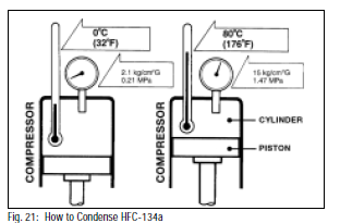
B. How to Condense Gaseous HFC-
134a Into Liquid
The air conditioning system cannot cool the
air when the liquid refrigerant is used up
(i.e. changed to the gaseous refrigerant.)
To change the gaseous refrigerant into a
liquid refrigerant, a compressor is used in
the car air conditioning.
As you know, when the gas is compressed
in the compressor, both the temperature
and pressure increase.
For example, when the gaseous refrigerant
is compressed from 2.1 kg/cm2 (0.21 MPa)
to 15 kg/cm2 (1.47 MPa), the temperature
also increases from 0°C to 80°C. (32°F to
176°F)
The boiling point of refrigerant at 15 kg/
cm2G (1.47 MPa) is 57°C (135°F). The
temperature 80°C (176°F) of compressed
gaseous refrigerant is higher than its
boiling point (57°C) and also higher than
the surrounding air. The refrigerant stays in
gaseous state.
C. Condensing the Gaseous HFC-134a
In the car air conditioning, the high pressure,
high temperature gaseous refrigerant
is transformed into a liquid by cooling it
down at the condenser.
By flowing through the condenser, the
compressed gaseous refrigerant releases
heat to the surrounding air and is condensed
back into a liquid. At this time, the
refrigerant temperature becomes lower
than the boiling point (around 57°C). The
liquid refrigerant then returns to the
receiver.

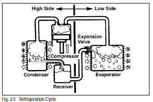
D. Refrigeration Cycle
1) The compressor discharges high
temperature and high pressure refrigerant
that contains the heat absorbed
from the evaporator plus the heat
created by the compressor in a
discharge stroke.
2) This gaseous refrigerant flows into the
condenser. In the condenser, the
gaseous refrigerant condenses into
liquid refrigerant.
3) This liquid refrigerant flows into the
receiver which stores and filters the
liquid refrigerant until the evaporator
requires the refrigerant.
4) After going through the expansion
valve, the liquid refrigerant changes
into low temperature, low pressure
liquid and gaseous mixture.
5) This cold and foggy refrigerant flows
into the evaporator. Vaporizing the
liquid in the evaporator, the heat from
the warm air stream passing through
the evaporator core is transferred to
the refrigerant.
All the liquid will change into the
gaseous refrigerant in the evaporator
and only the heat-laden gaseous
refrigerant is in the compressor. Then,
the cycle begins once again.
8. Automotive Refrigeration System
A. Basic Components
Compressor: It is critical that only gas be
drawn into the compressor. If liquid enters,
it will cause a hydrostatic lock in the
compressor and stall. The gas drawn in is
compressed to over 14.1 kg/cm2 (201 psi,
1.383 kPa), which becomes extremely hot.

Condenser: The condenser mounted at
the front of the coach acts as a radiator,
drawing off some of the heat of compression,
and changes the high temperature
gas into a liquid under high pressure.
When operating normally, the inlet of the
condenser is full of hot gas and the outlet
is full of hot liquid. There are some models
which are equipped with a fan exclusively
for the condenser

Receiver/Drier: The receiver is a part of the
system that is used to store the liquid
refrigerant.
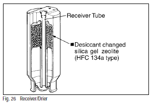
Also, the drier and filter in the receiver
remove the moisture and the dirt contained
in the refrigerant.
1) The receiver separates the gaseous
refrigerant from the liquid refrigerant
by the weight difference and ensures a
steady flow of liquid refrigerant be
supplied to the expansion valve.
2) The drier is simply a bag of desiccant,
such as zeolite, that is capable of
absorbing and holding moisture.
3) The sight glass is installed on the top
of the receiver. The refrigerant charge
amount is very important for the
efficiency of the air conditioner. The
sight glass is used to check the
amount of refrigerant. Also the sight
glass is installed on the high pressure
pipe between the receiver and the
expansion valve.
Expansion Valve: This small valve controls
the flow of refrigerant into the evaporator.
It is controlled by a temperature sensor at
the evaporator outlet. If the outlet temperature
is too high, it means not enough
refrigerant is flowing into the evaporator
and the result will be poor cooling.

If the outlet temperature is too cool, it
means too much refrigerant is flowing and
the evaporator fins will probably load up
with ice. In either case, the feedback
temperature sensor opens and closes the
expansion valve opening to achieve the
correct flow rate and evaporator outlet
temperature.
Evaporator: This is the last component in
the cycle, and where the air is finally
cooled. As the foggy mist of refrigerant
enters, the air passing over the evaporator
fins gives up its heat to evaporating
refrigerant. At the inlet the refrigerant is
liquid; it changes into gas at the outlet.

B. Automotive Refrigeration System
1. COMPRESSOR draws off gaseous refrigerant
from the evaporator and compresses
it. This causes the refrigerant gas temperature
and pressure to rise rapidly.
2. CONDENSER, through which the heated
refrigerant gas gives off heat to the engine
cooling air. The refrigerant gas cools off
and once again becomes a liquid.
3. RECEIVER/DRIER removes and traces of
moisture and filters out dirt in the system.
It also serves as a reservoir for excessive
refrigerant
4. EXPANSION VALVE controls liquid refrigerant
into the evaporator cores, causing a
drop in pressure and, consequently, a drop
in temperature.
5. EVAPORATOR, in which the released
refrigerant expands and flows through the
evaporator tubes. It removes heat from the
air blowing across the fins and tubes and
evaporates, causing the temperature
inside the car to be lowered gradually.

SAFETY PRECAUTIONS
1. Safety Precautions
When repairing air conditioning systems, the
following precautions and rules must be
observed.
A. Wiring
1) Isolate the negative battery terminal to
prevent short circuits.
2) All terminals and connectors should be
connected securely.
3) When wire harnesses are routed through
any hole in the vehicle, insert the rubber
bushing into the hole to protect harness.
4) The air conditioner wire harness should be
fastened to the main harness with the vinyl
tape or clamps.
5) If disconnecting or moving original harnesses
while repairing, they should be
returned to the proper position.
6) Be careful not to pinch the original air
conditioner wire harnesses when installing
or repairing air conditioner parts.
7) When the lead wire is added to the wire
harness by soldering, use the same or
larger diameter lead wire, and cover the
soldering position with the vinyl tape.
8) The wire harness should not be clamped
at any moving or high temperature components.
9) Connecting portion of wire harness must
be away from the joint of fuel pipe.
10) Be sure that the wire harness does not
touch the sharp corners or edges.
B. Piping
1) Never use a torch when bending tubes.
When bending tubes, try to make the
curve as wide as possible.
2) The insides of all air conditioner parts
must be free of moisture and dust. When
removing the piping parts, apply the blind
plugs or caps on the fittings.
3) When cutting tubes, dress off the tube
with a file, and clean the inside of tube of
all burrs.
4) Before making any hose and tube connections,
apply a few drops of refrigeration oil
to the seat of coupling nuts and O-rings.
5) When tightening and loosening fittings,
use two wrenches.
6) Pay special attention to the direction of
receiver. Receiver inlet fitting must be
connected to the tube from condenser
outlet fitting.
7) Tighten coupling nuts according to specified
torque

C. Refrigerant
1) The following rules must be followed when
handling refrigerant.
a) Use suitable eye protection such as
safety goggles or glasses when
handling the refrigeration or servicing
the refrigeration system.
b) Keep your skin from direct contact
with liquid refrigerant.
c) Do not heat the refrigerant container
above 40°C (104°F).
d) Do not discharge the refrigerant into
an enclosed area having an open
flame.
e) Do not allow the liquid refrigerant to
touch bright metal. Refrigerant in
combination with moisture is corrosive
and can tarnish bright metal and
chrome surfaces.
f) Discharge the refrigerant very slowly
when purging a refrigeration system.
Otherwise, the refrigeration oil will
discharge together with refrigerant.
2) If liquid refrigerant contacts your eye or
skin.
a) Do not rub the eye or skin.
b) Splash large quantities of cool water
to the eye or skin to raise the temperature.
c) Tape on a sterile eye patch to avoid
the possibility of dirt entering the eye.
d) Apply clean petroleum jelly to the skin.
e) Rush to a physician or hospital for
immediate professional treatment.
f) Do not attempt to treat the wound
yourself.
D. Safety Gaps
1) When installing the air conditioner parts,
keep safety gaps or use insulators which
do not interfere with surrounding parts.
a) Fan shroud—Radiator hose
5 mm (0.20 in.) or more
b) Cooling fan (steel)—Radiator
15 mm (0.59 in.) or more
Cooling fan (plastic)—Radiator
20 mm (0.79 in.) or more
c) Cooling fan—Fan shroud
15 mm (0.59 in.) or more
d) Cooling fan—Crankshaft and idle
pulleys
4 mm (0.16 in.) or more
e) Cooling fan—Radiator hose
15 mm (0.59 in.) or more
f) Brake and Fuel pipes—Surrounding parts
15 mm (0.59 in.) or more
g) Suction and discharge hoses—
Surrounding parts
15 mm (0.59 in.) or more (except
clamping position or using rubber
cushion)
h) High tension wire—Surrounding parts
15 mm (0.59 in.) or more
i) Loose side of V-belt—Radiator hose
20 mm (0.79 in.) or more
2) After finishing repair work, be sure that the
air conditioner parts do not touch the
surrounding parts of the vehicle.
E. Mounting Parts
1) Never forget the spring washer when
installing the parts so that the vibration
does not loosen the bolt.
2) Parts mounted on the engine must be
tightened to specified torque. (See vehicle
service manual).
F. Others
1) When repairing the air conditioning system,
use fender and seat covers to protect
the paint and upholstery.
2) When the air cleaner or water outlet are
removed from the engine, cover the engine
with the blind cover to keep free from dust
or dirt.
3) Never rotate the compressor if the refrigerant
is not charged into the refrigeration
system.
4) When storing the compressor as stock,
evacuate the inside and charge the
refrigerant or dry nitrogen about 1-2 kg/
cm2 (14-28 psi) into compressor to prevent
corrosion.
5) After finishing repair work, check if each
component part of the vehicle operates as
usual
2. Ultraviolet Rays and Ozone Layer
Specified chlorofluorocarbons, chemically
stable substances which are superior for heat
resistance and non-combustibility, have the
characteristics of being colorless and odorless
without being inflammable, corrosive, or toxic.
For these reasons, they came to be used for a
wide range of purposes such as refrigerants
for air conditioners and refrigeration units,
aerosol spray agents, cleaning agents for
electronic systems, fire extinguisher materials,
foam agents, and raw material for synthetic
resins.
On the contrary, the most important characteristic
of an alternative refrigerant is that the
ozone depletion potential is small, and the
indispensable minimum condition is that it can
be used safely in each area.
CFC-12, which is used as a refrigerant for
automotive air conditioners, is also subject to
restriction as a substance which depletes the
ozone. For an alternative substance which
doesn’t include chlorine, a source of ozone
depletion, HFC-134a is considered to be the
most suitable substance. Denso has developed
an automotive air conditioning system
which uses HFC-134a as a refrigerant in place
of CFC-12.
TOOLS AND EQUIPMENT
Service Tool and Testers
1. Service Tool Kit
A. Recovery/Recycling/Recharging Machine
B. Refrigerant Charging Hoses
C. Refrigerant Leak Tester

2) Handling of Service Tools
A. Manifold Gauge Set
NOTE: When recovery/recycling/recharging
equipment such as a Robinair Enviro
Charge Series 34700 or equivalent is used,
the manifold gauge set is included with the
system.
The hand valves (“LO” and “HI”) on the
manifold gauge set are used to open and
close the valve. The hand valve inscribed
“LO” is for the low pressure side valve and
“HI” is for the high pressure side valve.
(Fig. 31)

By opening or closing the high and low
pressure hand valves, the following
circuits are established.
1) When low pressure side valve (“LO”) is
opened and high pressure side valve
(“HI”) is closed.

2) When low pressure side valve (“LO”) is
closed and high pressure side valve
(“HI”) is opened.
Two circuits are established

3) When low and high pressure gauges
are closed.
Two circuits are established:

B. Refrigerant Charging Hose
The charging hoses are classified into
three colors.
Each charging hose must be handled as
follows:
1) The air conditioner manufacturer
recommends that the blue hose is
used for the low pressure side (suction
side), the green hose for refrigeration
side (center connecting port) and the
red hose for high pressure side
(discharge side).
2) HFC-134a charging hoses are
equipped with service couplers, which
allow you to install your charging
hoses to the charging valve on the
vehicle. These service couplers are
available from Robinair.

3) When the manifold gauge set is not in
use, connect the end of the hose to
the spare fitting of the refrigerant
charging hose. (Fig. 33)

C. Service Stop Valve
The service stop valve is used to prevent
leakage of refrigerant or oil when removing
the “HI” side charging hose for the compressor
provided with the schrader valve.
(Fig. 34)
1) How to Install
a) Before connecting the service stop
valve to the discharge service
valve of the compressor, turn the
hand valve completely counterclockwise.
b) Install the service stop valve to the
discharge service valve and
connect the “HI” side charging
hose to it.
c) Turn the hand valve clockwise until
the stem completely engages the
schrader valve.
2) How to Remove
a) Turn the hand valve completely
counter- clockwise.
b) Remove the service stop valve
from the discharge service valve.
c) Turn the hand valve clockwise
slightly to remove the residual
pressure in the charging hose.

D. Gas Leak Tester (Detector)
The conventional gas leak detectors such
as the halide torch type and electronic
type cannot be used to detect a gas leak
of HFC-134a. Since the conventional
detector easily detects chlorine (Cl), which
is contained in CFC-12 but not contained
in HFC-134a.
Therefore, a new gas leak detector has
been developed to detect HFC-134a
This new gas leak detector has a higher
degree of sensitivity to the presence of
HFC-134a and also can be used for CFC-
12. (Fig. 35)


3. Robinair Enviro Charge 34700 Series
This unit is the recommended A/C recover/
recycle station, it provides all-in-one service
for HFC-134a recovery, recycling and recharging.
A. Features
• Built-in manifold
• Microprocessor controls
• 4 cfm vacuum pump
• Refrigerant passes through the filter on the
way to the storage tank, providing UL
certified single pass recycling
• Automatic recycling of refrigerant while
system is being evacuated
• Moisture indicator changes color when
refrigerant is ready for reuse
• Refrigerant charge can be programmed or
controlled manually
• Automatic shut-off when all the refrigerant
has been pulled from the system
B. Specifications
Voltage 115 V 60 Hz
Refrigerant Tank One 50-lb. refill- able DOT ap- proved
Operating Range 50° to 120°F (11° to 49°C)
Recovery Rate 1/2 lb. per minute (.2 kg per minute)
Recycling Rate 1 lb. per minute flow rate
(.4 kg/min.) time depends on moisture content
Recycling Filter 43 cu. in. (710 cc) Quick Change
Scale Resolution 1/100 lb. Pump Free Air Displacement 4 cfm (93 L/M)
Dimensions 45” H x 22” W x 28” D
Weight 167 lbs. (76 kg)C. Replacement Parts
without tank
C. Replacement Parts
34430 Quick Change Recycling Filter
34750-50 Pound Refillable Tank
For additional information contact Robinair
at 1-800-368-6787.
TORQUE AND BOLT SPECIFATIONS
1. Standard Torque: Coupling Nut Type
Fittings

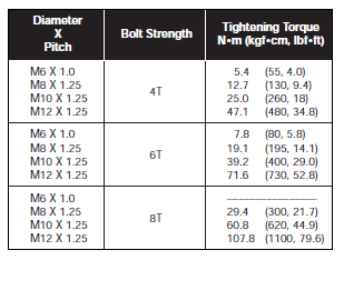
2. Torque Specification for Bolts/Nuts/
Screws

COMPONENT LOCATIONS AND POSITIONS
1. Interior Component Locations (All Models)
A. Heater and Cooling Unit

B. Cooling Unit Wire Harness

C. Dash Wire Harness and Control Panel

D. Temperature Control Cable
E. Fresh/Recirc. Damper Box

2. Raised Floor Measurements and Cutouts

TROUBLESHOOTING
1. Troubleshooting Table

2. Troubleshooting by Manifold Gauge

Condition A = Normal Reading
First, have the manifold gauge high and low
pressure side valves tightly closed, and connect
the charging hoses (red and blue) to the respective
compressor service valves.
In this case, if the service valves are the valve
plunger type, always make sure to set the plungers
to the intermediate seat position (slightly toward
back seat if the pointer vibrates) so as to enable
taking measurements with the gauges.
NOTE: Be sure to purge the air in the charging
hoses at the manifold gauge connection end by
utilizing the refrigerant pressure in the refrigerating
cycle.
If the refrigeration cycle is operating normally, the
reading at the low pressure side should generally
be around 21 ˜ 35 psi and at the high pressure side
around 199 ˜ 227 psi when ambient air temperature
is about 86° - 95°F, engine speed 1500 rpm,
strongest cooling setting, and blower operating at
top speed.
The gauge indications shown in the following
diagrams are taken under the same conditions
(ambient air 86° - 95°F, engine speed 1500 rpm,
strongest cooling setting, maximum blower speed),
so it should be noted that the gauge readings will
differ somewhat with the ambient conditions.
NOTE: Gauge should indicate static pressures
before A/C operation both high and low pressure
sides between 71~114 psi.

Condition B = Moisture Entered in the Cycle
Condition
1. Periodic cooling and no cooling at the evaporator.
Symptoms seen in refrigeration cycle
1. During operation, low side pressure alternately
becomes vacuum and normal.
When Abnormal:
Low Pressure Side: Vacuum
High Pressure Side: 99 ~ 142 psi
When Normal:
Low Pressure Side: 21 ~ 35 psi
High Pressure Side: 199 ~ 227 psi
Cause
1. The moisture in the refrigeration cycle freezes
in the expansion valve orifice and causes
temporary blocking.
After a time, the ice melts and condition
returns to normal.
Diagnosis
1. Receiver/drier in oversaturated condition.
2. Moisture in refrigeration cycle freezes expansion
valve orifice and obstructs refrigerant
circulation.
Remedy
1. Replace receiver/drier.
2. Remove moisture in cycle by means of repeated
evacuation.
3. Check expansion valve.
4. Recharge new refrigerant to the proper quantity.

Condition C = Insufficient Refrigerant
Condition
1. Would desire more cooling.
Symptoms seen in refrigeration cycle
1. High and low side pressures both low.
Low Pressure Side: 7 ~14 psi
High Pressure Side: 99 ~ 142 psi
2. Bubbles seen in sight glass.
3. Air discharged from air conditioner slightly
cold.
Cause
1. Gas leaking someplace in refrigeration cycle.
Diagnosis
1. Refrigerant in cycle insufficient.
2. Refrigerant leaking.
Remedy
1. Check for leakage with leak detector and
correct.
2. Evacuate and recharge refrigerant to proper
amount.

Condition D = Excessive Refrigerant or
Insufficient Condenser Cooling
Condition
1. Air conditioner fails to cool properly.
Symptoms seen in refrigeration cycle
1. High and low side pressures both high.
Low Pressure Side: 35 ~ 50 psi
High Pressure Side: 284 ~ 355 psi
2. Bubbles cannot be seen in the sight glass.
Cause
1. Due to overcharging refrigerant into cycle,
proper performance cannot be shown.
2. Condenser cooling faulty.
Diagnosis
1. Refrigerant overcharged.
2. Condenser cooling defective.
3. Condenser fins clogged or fan belt loose.
4. Radiator fan fluid coupling slipping or electric
fan inoperative.
Remedy
1. Clean condenser.
2. Adjust fan belt to proper tension.
3. If 1 and 2 are in normal condition, check
refrigerant quantity.
NOTE: If excessive refrigerant is to be discharged,
You must use a refrigerant recovery station.

Condition E = Air Entered in the Cycle
Condition
1. Air conditioner fails to cool sufficiently.
Symptoms seen in refrigeration cycles
1. High and low side pressures high.
Low Pressure Side: 35 ~ 43 psi
High Pressure Side: 284 ~ 355 psi.
2. Low pressure side piping not cold when
touched.
Cause
1. Air entered in refrigeration cycle.
Diagnosis
1. Air in refrigeration cycle.
2. Evacuating insufficient.
Remedy
1. Replace receiver.
2. Check compressor oil contamination and
quantity.
3. Recover refrigerant, evacuate and recharge
new refrigerant.
NOTE: The above cycle can be seen when after the
cycle is opened, the refrigerant is charged without
evacuation.

Condition F = Expansion Valve Trouble or
Improper Installation of Heat Sensitizing Tube
Condition
1. More cooling desired.
Symptoms seen in refrigeration cycle
1. Low and high side pressures both high.
Low Pressure Side: 35 ~ 43 psi
High Pressure Side: 284 ~ 355 psi.
2. Frost or heavy dew on low pressure side
piping.
Cause
1. Expansion valve trouble or heat sensitizing
tube improperly installed.
2. Flow adjustment not properly done.
Diagnosis
1. Excessive liquid refrigerant in low pressure
side piping.
2. Expansion valve opened too far.
Remedy
1. Check installed condition of heat sensitizing
tube.
2. If remedy 1 is in normal condition, replace
expansion valve.

Condition G = Refrigerant Fails to Circulate
Condition
1. Intermittent cooling
Symptoms seen in refrigeration cycle
1. Vacuum shown at low side and very low
pressure shown at high side.
Low Pressure Side: 27 in. Hg
High Pressure Side: 71 ~ 85 psi
2. Frost or dew formed on piping at inlet and
outlet of expansion valve or receiver.
Cause
1. Refrigerant flow obstructed by moisture or dirt
in the refrigerating cycle freezing or sticking on
the expansion valve orifice.
Diagnosis
1. Expansion valve orifice plugged.
2. Refrigerant does not circulate.
Remedy
1. Allow to stand for some time and then resume
operation to decide whether the plugging is
due to moisture or dirt.
a. If caused by moisture – Correct by referring
to instructions in condition B.
b. If caused by dirt – Remove the expansion
valve and blow out the dirt with compressed
air. If unable to remove the dirt,
replace the expansion valve. Replace the
receiver. Evacuate and recharge proper
amount of new refrigerant.
c. If caused by gas leakage in heat sensitizing
tube Replace the expansion valve.

Condition H = Faulty Compression of
Compressor
Condition
1. Does not cool.
Symptoms seen in refrigerating cycle
1. Low pressure side pressure too high.
2. High pressure side pressure too low.
3. Low pressure side: 56~85 psi
4. High pressure side: 99~142 psi
Cause
1. Leak in compressor.
Diagnosis
1. Compression faulty.
2. Valve leaking or broken, sliding parts (piston,
cylinder, gasket, connecting rod, etc.) broken
3. Visual and Audible Troubleshooting
Questions
A. Are there any loose V-belts?
If the V-belt is loose, it will slip and wear
out faster. Adjust to the recommended
tension or replace with a new V-belt if
worn out.
B. What if you hear noise near the compressor?
Check the compressor mounting bolts and
the bracket mounting bolts to see if they
are loose. Tighten all loose bolts.
C. Do you hear noise inside the compressor?
This could be caused by a worn bearing or
lack of refrigeration oil in system. Remove
the compressor, disassemble, and make
all necessary repairs or replacements.
D. Are condenser fins covered with dirt and
dust?
If the condenser fins are dirty, the cooling
effect will be greatly reduced. To prevent
this from happening, wash off all dirt and
dust. Be careful not to damage or bend
fins if you are using a stiff brush to wash
condenser.
E. Do you see oil stains in the refrigerating
cycle connections and joints?
Any place where an oil stain can be seen
usually indicates that refrigerant is leaking
from that spot. This is because the compressor
oil and the refrigerant will escape
out of the system together. Thus, the
location of the leak can be pinpointed by
the spot where the oil stain is found. At
this spot, all bolts should be retightened to
the proper torque and parts replaced, if
needed, to stop the leak.
Since compressor gasket joints and pipe
connectors are the most likely spots where
oil stains are found, special attention
should be given to checking these places.
F. Do you hear noise near blower?
Turn the blower motor to LOW, MEDIUM
and HIGH speeds. If you hear any unusual
sounds or the motor rotation appears
defective, make sure there are no foreign
objects lodged in the blower or loose bolts
and parts which need tightening as this
can sometimes be the cause of these
problems.
If no foreign objects are found, replace the
blower motor.
G. What should you see when checking
refrigerant quantity at sight glass?
If a large flow of bubbles can be seen in
the sight glass, there is insufficient refrigerant
charged. Refrigerant should be replenished
to its proper level. Also check for oil
stains (as described previously) to make
sure there is no refrigerant leak.
If bubbles cannot be seen in the sight
glass, even when the condenser is cooled
by pouring water, this is a sign that there is
too much refrigerant in the system. Therefore,
the excessive amount should be
removed/recovered. One should be very
careful when taking out refrigerant from
the low pressure side service valve to
avoid removing too much which may
cause the compressor oil to blow out.
4. Troubleshooting Chart
CAUTION: When repairs are required on the compressor, condenser, discharge hose, receiver/
drier, or the condenser fan motor, please refer to the appropriate chassis manufacturer repair
manual.

5. Insufficient Cooling
A. Compressor


B. Magnetic Clutch

C. Expansion Valve

6. Abnormal Noise

COMPONENT TESTING
Note: Please refer to the appropriate GM, Ford,
Freightliner, or Spartan (thru mid-1998) manuals
when On-Vehicle Diagnosis indicates that the
problem is caused by the following components:
1. Compressor and Magnetic Clutch
2. Receiver/Drier
3. Models with Electric Fan Motor for Condenser
1. Blower/Cooling Unit
A. On Vehicle Inspection of Expansion
Valve
Inspect A/C system visually and audibly.
Next, inspect the system with a ROBINAIR
(manifold gauge) or equivalent equipment.
1) While turning A/C switch “ON” and
BLOWER switch “HI”, run engine at
1,500 RPM for at least five (5) minutes
and check A/C performance in
RECIRC mode.
2) If expansion valve is clogged, the low
pressure reading will drop. If normal,
the pressure will remain the same.
3) If the low pressure reading is normal
and A/C is not cooling, check for
malfunction of expansion valve.
B. Blower/Cooling Unit Removal
1) Disconnect negative cable from
battery.

2) Remove refrigerant from the system using
ROBINAIR or equivalent equipment.
3) Remove HVAC cover on passenger
side.

4) Remove fresh/recirculate air box. (Fig. 54)
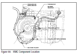
5) Disconnect wire harness at: (Fig. 55)
• Three (3) relays
• Blower
• Servo motor
• Two (2) connectors from thermostat
• Blower resistor
• Fresh/recirculate connector
• Pressure switch
• Main harness connector

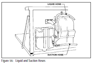
6) Remove suction and liquid lines from
cooling unit. (Fig. 56)
NOTE: Seal lines to prevent moisture
from entering into the A/C system
7) Remove bracket from heater to
evaporator case. (Fig. 57)
8) Remove the six (6) mounting screws
and washers holding the blower/
cooling unit to the bulkhead. (Fig. 57)

9) Remove passenger far-right air vent
grille assembly.
10) Remove screw securing the heater
unit by reaching through the vent hole
in the upper right corner of the dash.
11) Loosen the two (2) screws securing
the heater unit to the engine compartment
cover (or wood support - diesel
models).
NOTE: These two screws may be removed
by lifting the instrument panel and reaching
under the dashboard (or HVAC cover
on diesel models).
12) Carefully slide blower/cooling unit
assembly rearward.
C. Blower/Cooling Unit Disassembly
(Fig. 58)

1) Remove three (3) blower motor mounting
screws from the case.
2) Remove blower motor vent tube from
upper case.
3) Remove blower motor.
4) Remove thermostat from upper case.
5) Remove nine (9) screws from cooling
unit case.
6) Remove two (2) clips from cooling unit
case.
7) Remove upper and lower case halves
from evaporator core.
8) Remove packing from expansion valve
sensing tube located on the evaporator
suction tube.
9) Remove “C” clip from sensing tube.
10) Disconnect liquid tube from the inlet
fitting of the expansion valve.
11) Remove expansion valve.
D. Evaporator Core Inspection
1) Inspect evaporator core fins for
blockage.
• If fins are clogged, clean with
compressed air.
• Do not use water to clean evaporator
core.
2) Inspect fittings for cracks or
scratches. Repair or replace as
required.
E. Blower/Cooling Unit Assembly
(Fig. 59)
1) Connect the expansion valve to the
evaporator and torque to 23 N•m (235
kgf•cm, 17 lbf•ft).

2) Install expansion valve sensing bulb to
evaporator suction tube with “C” clip
and insulate with packing.
3) Connect the liquid tube to the evaporator
core and torque to 13 N•m (135
kgf•cm, 10 lbf•ft).
4) Install lower case.
5) Install thermostat.
6) Install upper case.
7) Install nine (9) screws.
8) Install two (2) clips.
9) Install blower motor and vent tube.
10) Reconnect wire harness. (Fig. 60)

F. Blower/Cooling Unit Installation
1) Install blower/cooling unit with six (6)
screws.
2) Install heater to evaporator case
bracket.
3) Reconnect wire harness. (Fig. 60)
4) Reconnect suction hose and torque to
32 N•m (325 kgf•cm, 24 lbf•ft)
5) Reconnect liquid hose and torque to
13 N•m (135 kgf•cm, 10 lbf•ft).
6) Install fresh/recirculate air box.
7) Install HVAC cover.
8) Reconnect negative cable to battery.
9) Evacuate and charge using ROBINAIR
or equivalent equipment.
2. Compressor Fitting
NOTE: DENSO supplied a suction side compressor
fitting on Ford chassis thru mid-1996
model year.

A. On Vehicle Inspection
1) Inspect service valves for leakage
using a gas leak detector.
2) Replace if necessary
B. Replacement
1) Recover refrigerant from system.
2) Replace failed part and torque to 32
N•m (325 kgf•cm, 24 lbf•ft).
3) Evacuate and charge using Robinair
charging station or equivalent
3. Refrigerant Hoses/Tubes
A. On Vehicle Inspection
1) Inspect hoses/tubes for leakage using
a gas leak detector.
2) Replace if necessary.
B. Replacement
1) Recover refrigerant from system.
2) Replace failed part and torque to
proper spec.
• Suction Hose 32 N•m (325
kgf•cm, 24 lbf•ft)
• Liquid Hose 13 N•m (135 kgf•cm,
10 lbf•ft)
3) Evacuate and charge using Robinair
charging station or equivalent.
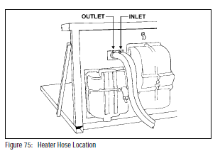
4. Heater Hoses: On Vehicle Inspection
A. Inspect hoses for leakage.
B. Replace if necessary.
(Only Ford and GM chassis heater hoses
are DENSO supplied.)


5. Heater
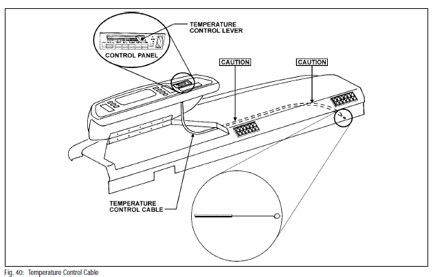
A. On Vehicle Inspection and Adjustment
1) Inspect HVAC control panel. Move the
temperature control lever to see if
cable moves freely without binding
and has full range of travel.

2) Check routing of the temperature
control cable so it is free of any sharp
bends or interference with linkages.

B. Control Cable Adjustment
NOTE: On the control panel, check that the
control cable insulation extrudes no less than
1/16” past the metal clamp on the control panel
mounting base. If less than 1/16”, go to next
step. (Fig. 69)

1) Loosen the tapping screw and push
the control cable insulation forward
past the metal clamp approximately
1/16”. Retighten the tapping screw.
CAUTION: Do not overtighten the tapping
screw. This could result in damage to the
mounting base of the control panel.
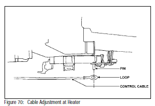
2) On the bottom of the HVAC unit,
locate the spring clip and carefully
remove the control cable insulation.
(Fig. 70)
3) Move the temperature control lever on
the control panel to the maximum cool
position (all the way to the left). (Fig. 71)

4) Looking at the bottom of the HVAC
unit, push and hold the cam le
ver with
the control cable attached to the pin to
maximum cool (clockwise) position.
(Fig. 72)

5) While holding the cam lever in the
proper position, recheck that the
temperature control lever on the
control panel is in the maximum cool
position. (Fig. 71)
6) While holding the cam lever in the
maximum cool position, snap the
control cable insulation into the spring
clip by pushing upward. (Fig. 73)

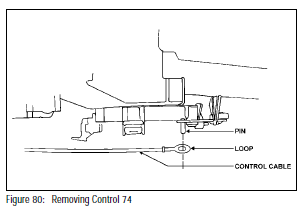
C. Heater Core Removal
1) Remove blower/cooling unit case (see
page 40).
2) Remove control cable from heater
unit. (Fig. 74)
3) Remove heater hose from heater core.
NOTE: Hoses should be marked so they
can be easily identified and reconnected to
their proper connections.
4) Remove temperature control damper
door cam which is secured by one (1)
screw with a plastic washer.
CAUTION: Do not attempt to remove heater
core without removing damper door cam.
5) Remove plastic lever which is
mounted over heater core.

6) Remove heater core support bracket.
7) Remove heater core tube bracket.
8) Carefully slide the heater casing
backwards toward the passenger
compartment until the heater core
tubes are clear of the bulkhead.
9) Pull out the heater core by sliding the
unit downward and away from the
heater core case.
D. Heater Core Inspection
Inspect the heater core and repair or replace
as required
E. Heater Core Installation
Follow reversal of steps for removal.
6. Thermostat
A. Thermostat Operation
The thermostat is wired in series with the
high-low side of the pressure switch and
prevents the evaporator from freezing over
by controlling the ground to the coil of the
magnetic clutch relay.
When the thermostat is set to the max cold
position (full clockwise), the thermostat
contacts will be closed at evaporator
temperatures above 4.5°C (40.1°F) and open
between 1°C and 25°C (32.9°F and 36.5°F).
When the thermostat is set to the max
warm position (full counterclockwise), the
contacts will be closed at evaporator
temperatures above 7.5°C (45.5°F).
If the thermostat does not perform as
specified, replace the thermostat.
NOTE: The thermostat is preset at the
factory and should not be adjusted. This
information is supplied for diagnostic
purposes only.
B. Thermostat Removal
1) Remove and disassemble blower/
cooling unit.
2) Remove thermostat from unit.

C. Thermostat Installation
Follow reversal of steps for removal
7. A/C Control System: On Vehicle
Inspection
A. Inspect A/C Switch for continuity.
B. Inspect A/C Blower Speed Control Switch
for continuity.
C. A/C Control Levers Inspection
1) Inspect the control lever at control
panel for smooth operation.
2) Inspect the control lever at HVAC for
smooth operation


D. A/C Control Cable Inspection
Inspect control cable for proper adjustment
and kinks.
8. Control Panel Removal
A. Disconnect negative cable from battery.
B. Open instrument control panel (if equipped).

C. Remove four (4) screws on control panel
bezel plate (if equipped). (Fig. 80)

D. Remove control panel from rear of dash
panel.
E. Remove control cable from control panel.
(Fig. 81)

F. Remove two (2) wire harness connectors
from control panel.

G. Remove and save metal support bracket
from control panel (if equipped).

A. Inspection
Inspect control panel for continuity.

B. Installation
Follow reversal of steps for removal.
NOTE: See Control cable adjustment on
page 43.
9. Pressure Switch
A. Pressure Switch Operation
The pressure switch is a triple pressure
switch with a high and low pressure set of
contacts and a medium pressure set of
contacts. The high-low side is wired in series
with the thermostat and controls the ground
to the coil of the magnetic clutch relay. On
vehicles equipped with a condenser fan, the
medium side is wired in parallel with the
water temperature switch and controls the
ground to the coil of the condenser fan relay.
B. On Vehicle Inspection
1) Disconnect negative cable from
battery.
2) Remove HVAC cover on passenger
side.
3) Confirm refrigerant charge status with
ROBINAIR or equivalent equipment.
4) Disconnect the pressure switch
harness connector from the cooling
unit harness.

5) Connect a jumper wire between
terminals 13B and 14A of the cooling
unit harness.

6) With the A/C system at normal operating
pressures, check for continuity
between terminals 41A and 42A for
the high-low side and terminals 43A
and 44A for the medium side.
7) If there is no continuity, replace the
switch.
C. Pressure Switch Removal
1) Remove and disassemble blower/
cooling unit. (Fig. 87)

2) Remove wire harness from pressure
switch.
3) Remove pressure switch from liquid line.
D. Installation
Follow reversal of steps for removal.
10. Blower
A. On Vehicle Inspection
1) Blower and Fan Operation
Connect positive (+) lead from battery
to terminal #1 and negative (-) lead to
terminal #2 to confirm smooth operation
of motor.

2) Blower Resistor Inspection.
Inspect the resistor for specification.

B. Blower and Fan Removal
1) Disconnect negative cable from
battery.
2) Remove HVAC cover on passenger
side.
3) Remove blower motor 2-pin connector.
4) Remove blower motor vent tube.
5) Remove three (3) screws mounting
blower motor to the case.
6) Remove the blower motor and fan.
NOTE: If the blower motor or fan
replacement is required, follow the
steps below.
a) Remove clip from fan.
b) Remove fan from blower motor.
c) Replace fan or blower motor as
required
C. Blower Resistor Removal
1) Disconnect negative cable from
battery.
2) Remove HVAC cover on passenger side.
3) Disconnect 4-pin connector from
blower resistor.
4) Remove two (2) screws from blower
resistor.
5) Remove blower resistor.
D. Installation
Follow reversal of steps for removal.
11. Relays
Remove HVAC cover on passenger side to
access the following three (3) relays:
A. Main Relay
Inspect five 5-pin main relay for continuity
and replace the relay as required

B. Blower HI Relay
Inspect 4-pin Blower HI Relay for continuity
and replace the relay as required.

C. Mg/Cl (Magnetic Clutch Relay)
Inspect 4-pin Mg/Cl Relay for continuity
and replace the relay as required.

12. Air Intake Servo
A. Air Intake Servo Operation
The air intake servo changes the air intake
door between the FRESH and RECIRC
positions by rotating 180° in the clockwise
direction every time the RECIRC switch on
the control panel is depressed (RECIRC
mode) or released (FRESH mode).
NOTE: To check for proper operation of
the Air Intake Servo, the ignition switch
must be in the “ON” position.
B. Air Intake (Air Box Fresh/Recirculate)
Servo Removal
1) Remove HVAC cover on passenger
side to access the servo.
2) Disconnect negative cable from
battery.
3) Disconnect connector for air box
fresh/recirculate servo motor.
4) Remove fresh/recirc air box.
5) Remove linkage rod from servo motor.
6) Remove wire harness from servo
motor.
7) Remove two (2) screws from servo
motor.
8) Remove servo motor from air box.
C. Air Intake Servo Inspection
Check continuity of the servo according to
the chart as shown.

D. Air Intake Servo Installation
Follow reversal of steps for removal.
13. Vent Mode Servo
A. Vent Mode Servo Operation
The mode servo controls the distribution
of outlet air between vent/face, bi-level,
foot, or defrost.

B. Vent Mode Servo Motor Removal
1) Remove HVAC cover on passenger
side to access the servo.
2) Disconnect negative cable from
battery.
3) Remove passenger side floor/vent
cover.
4) Remove wire harness from servo
motor.
5) Remove linkage from servo motor.
6) Remove three (3) mounting screws
from servo motor.
7) Remove servo motor.
C. Vent Mode Servo Inspection
1) With the harness connected and the
ignition switch in the “ON” position,
verify the following lever positions by
depressing the corresponding control
panel mode switch.

2) If no movement is detected, check the
following conditions:
a) Battery voltage between pins 2D
and 5A.
b) Continuity of both wire harnesses
between the mode servo connector
and control panel connector.
c) Continuity of the control panel.
(Refer to the control panel testing
section).
D. Vent Mode Installation
Follow reversal of steps for removal.
REFRIGERANT LINE REPLACEMENT
1. On Vehicle Inspection
A. Check that hose and tube connections are
not loose.
B. Inspect hoses and tube for leakage.
• Use an electronic gas leak detector to
check for leakage of refrigerant in the
A/C system.
2. Refrigerant Lines Replacement
A. Recover refrigerant from A/C system.
Use a ROBINAIR or equivalent Recovery/
Recycling Machine to recover refrigerant in
the system before removing any component
to prevent any release of refrigerant
into the atmosphere.
B. Immediately cap the open fittings to
prevent moisture, dust and air from
entering the system.
DO NOT REMOVE the end caps on
replacement hoses until just before
installation.
C. Replace faulty components as required.
D. Before connecting, apply a few drops of
compressor lubricant to “O” rings and
coupling nut fittings.
E. Securely torque connections to specifications
to assure there is no refrigerant leak.
Be sure to use two (2) wrenches to avoid
twisting tubes.
F. Evacuate air in the system and recharge.
G. Inspect for leakage with electronic leak
detector.
H. Check air conditioning system operation
and performance.
3. Torque Specifications
A. Standard Torque for Coupling
Nut Type Fittings

B. Torque Specification for Bolts/
Nuts/Screws
4. CHASSIS
A. GM Chassis: Liquid, Suction, and Heater Hoses (thru mid-1996)

B. GM L29 Chassis: Liquid, Suction, and Heater Hoses (from mid-1996)

C. GM P12 Chassis
Liquid, Suction, and Heater Hoses

D. Ford Chassis (thru mid-1998)
Liquid, Suction, and Heater Hoses

E. Ford Chassis (from mid-1998)
Liquid, Suction, and Heater Hoses

F. Freightliner Chassis/Spartan Chassis (thru mid-1998)
1) Liquid and Suction Hoses

2) Suction Tube

G. Spartan Chassis (mid-1998 and on)


(1) Drive Belt Tension
(a) Check belt tension using a belt
tension gauge.
Belt Tension: 80 ± 10 lbs.
(b) Adjust as needed by loosening
idle pulley lock nut and turning
adjusting bolt until belt reaches
specified tension.
(c) Tighten and torque the idle pulley
lock nut.
Tightening Torque: 39.2 N•m (29
lbf•ft)
(2) On Vehicle Inspection: Compressor
Magnetic Clutch
(a) Inspect compressor and clutch
assembly for signs of oil.
(b) Check clutch bearings for abnormal
noise, grease leakage, or
excessive play.
(c) Check if clutch is energized when
positive (+) lead from battery is
applied directly to the clutch lead
wire and negative (-) lead to the
clutch ground wire.
(d) Measure resistance of the stator
coil using an ohmmeter.
Standard Resistance @ 20°C
(68°F): 3.75 ± 0.2Ω
(3) On Vehicle Inspection: Compressor
(a) Install manifold gauge set.
(b) Run engine at approximately 1,500
RPM with compressor engaged.
(c) Check for abnormal noise or
abnormal pressures (high side too
low and low side too high).
(d) With engine off, check for any
leakage from shaft seal on compressor.
If defects are found,
replace compressor.
(4) Compressor Removal
(a) Run engine at idle with A/C on for
approximately 5–10 minutes.
(b) Stop engine.
(c) Disconnect negative battery cable.
(d) Disconnect clutch lead wire.
(e) Recover refrigerant from A/C
system.
(f) Disconnect compressor hoses.
CAUTION: Cap ends of hoses IMMEDIATELY
after disconnecting from compressor to prevent
moisture or other contaminants from
entering the system.
(g) Loosen compressor belt.
(h) Remove compressor mounting
bolts and the compressor

(5) Magnetic Clutch Disassembly
(a) Remove the shaft bolt.
(b) Remove the pressure plate.
(c) Remove the shims from the
pressure plate.
(d) Remove the snap ring that secures
the rotor.
(e) Remove the rotor from the compressor
shaft by carefully tapping
with a plastic hammer.
(f) Disconnect stator lead wire from
the compressor body.
(g) Remove the snap ring that secures
the stator.
(h) Remove the stator.
(6) Magnetic Clutch Assembly
Follow the steps in Paragraph (5) in
reverse order for assembly.
IMPORTANT: DO NOT reuse snap rings. Use
new snap rings to secure rotor and stator.
Shaft Bolt Tightening Torque: 14 N•m
(10 lbf•ft)
Check air gap between pressure plate
and rotor.
Standard Clearance: 0.5 ± 0.15 mm
(0.020 ± 0.0059 in.)
If the clearance is not within specified
range, change the number of shims
until the required clearance is reached.
(7) Compressor Installation
Follow the steps in Paragraph (4) in
reverse order for installation.
Tightening Torques:
Compressor Mounting Bolts: 24.5
N•m (18.1 lbf•ft)
Compressor Hoses: 9.8 N•m (7.2
lbf•ft)
After installation, evacuate air in the
system and recharge.
HFC-134a: 48oz. ± 2 oz.
Inspect system for leaks using a
refrigerant leak detector. Check air
conditioning system for proper operation
and performance.


(8) On Vehicle Inspection: Condenser Fan
(a) Check if condenser fan operates when air conditioning system is on. If fan is rotating in the
proper direction, it will be pulling air through the condenser.
(b) Check if the fan operates when the positive (+) lead wire from the battery is applied directly
to the fan wire and the negative (-) lead wire is applied to the fan ground wire. If the fan fails
to operate when wired directly, replace the fan. If fan operates normally when wired directly
but fails to operate when air conditioning system is on, confirm proper wiring connection
where interface harness (including condenser fan relay) connects dash A/C to chassis.
The dash A/C system output (to energize the magnetic clutch) is the black wire with white
tracer (BW). It is also used to energize the condenser fan relay.
(9) Condenser Fan Removal
(a) Disconnect 2-Pin connector from
fan.
(b) Remove four (4) nuts securing fan
to fan bracket.
(c) Remove fan.

(10) On Vehicle Inspection: Condenser
(a) Inspect condenser fins for blockage or damage. If clogged, wash with water and blow with
compressed air. If fins are bent, straighten with a fin straightening tool.
(b) Check hose connections for leakage using a refrigerant leak detector. Repair as needed.
(11)Condenser Removal
(a) Recover refrigerant from air
conditioning system.
(b) Disconnect hoses from condenser.
CAUTION: Cap ends of hoses IMMEDIATELY
after disconnecting from condenser to prevent
moisture or other contaminants from entering
the system.
(c) Disconnect 2-Pin connector from
condenser fan.
(d) Remove fan and fan bracket
together by removing two (2) nuts
and two (2) bolts securing fan
bracket to condenser bracket.
(e) Remove two (2) bolts securing
condenser to upper condenser
bracket.
(f) Remove bolts securing upper
condenser bracket to frame rails
and slide bracket forward.
(g) Lift condenser out of lower
bracket and remove.
(12)Condenser Installation
Follow the steps in Paragraph 11 in
reverse order for installation.
Tightening Torques:
Upper Condenser Bracket to Side
Rails: 280 N•m (200 lbf•ft)
Discharge Hose: 9.8 N•m (7.2 lbf•ft)
Liquid Hose: 7.8 N•m (5.8 lbf•ft)
If the condenser was replaced, add oil
to compressor.
ND Oil 8: 40–50 cc (1.4–1.7 oz.)
After installation, evacuate the system
and recharge.
HFC-134a: 48 oz. ± 2 oz.
Inspect system for leaks with a refrigerant
leak detector. Check the system
for proper operation and performance

(13)On Vehicle Inspection: Receiver/Drier
(a) Check that bolts securing hoses and tubes are not loose.
(b) Check connections for leakage with a refrigerant leak detector and repair if needed.
(14)Receiver/Drier Removal
(a) Recover refrigerant from A/C
system.
(b) Disconnect hoses from receiver/
drier.
CAUTION: Cap ends of hoses IMMEDIATELY
after disconnecting from condenser to prevent
moisture or other contaminants from entering
the system.
(c) Remove receiver/drier from
receiver/drier bracket.
(15)Receiver/Drier Installation
Follow the steps in Paragraph 14 in
reverse order for installation.
Tightening Torques for Liquid Hoses:
5.4 N•m (4.0 lbf•ft)
If the receiver/drier was replaced, add
oil to the compressor.
ND Oil 8: 20 cc (0.7 oz.)
After installation, evacuate the system
and recharge.
HFC-134a: 48 oz. ±2 oz.
Inspect system for leaks with a refrigerant
leak detector. Check the system
for proper operation and performance.

REFRIGERANT CHARGING
1. About Certification
A. Ozone Layer and CFCs
Recent scientific findings indicate that
CFCs, like CFC-12 as well as bromines
from halons used in fire extinguishers, are
depleting the Earth’s protective ozone
layer located in the stratosphere some 10
to 30 miles above this planet’s surface.
This ozone layer filters out most of the
harmful ultraviolet rays from the sun.
B. Montreal Protocol
In 1985 scientists confirmed a large hole in
the ozone layer and on September 16,
1987, the United States and 22 industrial
countries signed an agreement in
Montreal, Canada, known as the “Montreal
Protocol”.
This agreement restricted CFC production
to 1986 levels beginning from July 1989.
C. London Meeting
Because the ozone layer depletion was
worse than predicted, a reassessment
meeting was held in London in June 1990.
At this meeting all the member nations
agreed to accelerated cutbacks of CFCs
with a total phaseout by the year 2000.
D. Federal Clean Air Act
In relation to these agreements, President
Bush signed Section 609 of the amended
Clean Air Act on November 15, 1990.
The Section 609 states that persons
servicing motor vehicle air conditioning
systems must be properly trained and
certified.
Some states and jurisdictions have
adopted their own deadlines and regulations
in addition to federal requirements.
Effective January 1, 1990 the federal law
requires that:
1. Each affected establishment shall
certify that the establishment has
acquired and is properly using approved
refrigerant recycling equipment.
2. Each person authorized by the establishment
to perform that service must
be properly trained and certified.
E. SAE Standards
SAE (The Society of Automotive Engineers)
established 3 standards regarding
refrigerant recovery and recycling, all of
which are mentioned in Section 609 of the
Clean Air Act.
J1989 Standard
This standard establishes guidelines for
the use of recovery/recycling equipment
when servicing automotive air-conditioning
systems.
J1990 Standard
This standard is for equipment and all
recovery/recycling equipment must meet
SAE J1990.
J1991 Standard
This standard is for a purity of recycled
refrigerant and recovery/recycling equipment
must have UL (Underwriter’s Laboratories)
approval to meet J1991.
2. Section 609 of the Clean Air Act
Amendments of 1990
The most important part of the amendments to
Section 609 of the Federal Clean Air Act have
to do with servicing motor vehicle air conditioning
and technician certification. The act
states:
Servicing Motor Vehicle Air Conditioners–
Effective January 1, 1992, no person repairing
or servicing motor vehicles for consideration
may perform any service on a motor vehicle air
conditioner involving the refrigerant for such
air conditioner without properly using approved
refrigerant recycling equipment and no
such service unless such person has been
properly trained and certified. The requirements
of the previous sentence shall not apply
until January 1, 1993 in the case of a person
repairing or servicing motor vehicles for
consideration at an entity which performed
service on fewer than 100 motor vehicle air
conditioners during calendar year 1990 and if
such person so certifies to the Administrator
by January 1, 1992.
Certification
(1) . . . each person performing service on
motor vehicle air conditioners for consideration
shall certify to the Administrator–
that such person has acquired, and is
properly using, approved refrigerant
recycling equipment in service on motor
vehicle air conditioners involving refrigerant
and that each individual authorized by
such person to perform such service is
properly trained and certified;
(2) Effective January 1, 1993 each person . . .
Shall submit a certification under paragraph
(1) (A).
(3) Each certification under this subsection
shall contain the name and address of the
person certifying under this subsection
and the serial number of each unit of
approved recycling equipment acquired by
such person and shall be signed and
attested by the owner or another responsible
officer. Certifications under paragraph
(1)(A) may be made by submitting
the required information to the Administrator
on a standard form provided by the
manufacturer or certified refrigerant
recycling equipment
3. Evacuating and Charging Refrigerant
CAUTION: To prevent the release of refrigerant
into the atmosphere, charging hoses equipped
with stop valves must be used when installing
the manifold gauge set to the A/C system.
A. Install Manifold Gauge Set With
Stop Valves
Make sure the correct hoses are connected
to the high pressure sides and low
pressure sides.
Do not apply lubricant to connection
seating area.
1) Close the stop valves on manifold
gauge charging hoses.
2) Close both shut-off valves on manifold
gauge set.
3) Remove caps from charge ports and stop
valves on compressor service valves.
4) Connect charging hoses with stop
valves to charge ports.
a) Tighten fittings by hand.
b) Make sure the correct hoses are
connected to the high pressure
side and low pressure sides.
c) Do not apply lubricant to connection
seating area.
NOTE: On Ford Chassis (with stop valve on
compressor fitting) viewed from the rear of engine,
turn the stop valve in the clockwise direction four
full turns (half open).
5) Open stop valves on both charging hoses.


B. Evacuate Refrigeration System
1) Connect the center hose of the
manifold gauge set to the vacuum
pump. (Fig. 123)
2) Open both high and low hand valves;
then run the vacuum pump.
NOTE: If opening the low pressure hand valve
causes the high pressure gauge to go into the
vacuum range, this does not mean there is blockage
in the system.
3) After ten (10) minutes or more, make
sure the low pressure gauge indicates
750 mmHg (30 in. Hg) or more of
vacuum.
NOTE: If the reading is not 750 mmHg (30 in. Hg)
or more of vacuum, close both hand valves of the
manifold gauge set and stop vacuum pump. Check
the system for leaks and make necessary repairs.
4) Close both high and low hand valves;
then stop the vacuum pump.
5) Leave the system in this condition for
five (5) minutes or longer, and check
that there is no change in the gauge
indicator

C. Install Charging Cylinder
NOTE: When handling the charging cylinder,
always follow the directions given in the instruction
manual.
1) Charge the proper amount of refrigerant
in charging cylinder.
2) Connect the center hose to charging
cylinder
CAUTION: Do not open both high and low
hand valves of manifold gauge set.
3) Press on the schrader valve, which is
on the side of the manifold gauge, and
expel the air inside the center hose.
(Fig. 124)
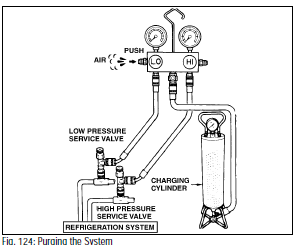
D. Inspect Refrigeration System for
Leaks
After evacuating the air in system, check
the system for leakage.
1) Open the high pressure hand valve
and charge refrigerant.
2) When the low pressure gauge indicates
98 KPa (1 kg/cm2, 14 Psi), close
the high pressure hand valve.
3) Using a leak detector, check the
system for leaks.
4) If a leak is found, repair the faulty
component or connection, and evacuate
air in refrigerant system.
CAUTION: Use refrigerant recovery/recycling
machine to recover the refrigerant when replacing
parts.

E. Charge Refrigerant Into Refrigerant
System
After refrigerant leak check, if there is no
leak, charge the proper amount of refrigerant
into the refrigeration system.
CAUTION: Never run the engine when charging
the system through the high pressure side
and do not open the low pressure hand valve
when the system is being charged with liquid
refrigerant.
1) Open the high pressure hand valve
completely.
2) Charge specified amount of refrigerant;
then close the high pressure hand
valve.
NOTE: A fully charged system is indicated by the
sight glass being free of any bubbles.
(See the following Refrigerant Volume Section for
Sight Glass Inspection.

F. Remove Manifold Gauge Set
From Service Valves
1) Close both hand valves of manifold
gauge set.
2) Close hand valves of both stop valves.
NOTE: On Ford chassis (with stop valve on compressor
fitting) turn the stop valve in the counter
clockwise direction until it is fully back seated (four
turns).
3) Disconnect charging hoses from
charging ports on compressor service
valves.
G. Install Caps to charge ports and
stop valves on compressor service
valves
4. Refrigerant Volume
A. Refrigerant Volume Inspection
1) Run engine at approximately 1,500
RPM.
2) Operate A/C “ON” and Blower “HI” for
at least five (5) minutes.
3) Open front hood and inspect sight
glass on the receiver/drier for the
following conditions:
a) Bubbles in Sight Glass
Refrigerant = Insufficient
Bubbles in sight glass may indicate
normal when ambient temperature
is higher than 95°F (35°C)
if the A/C cooling performance is
satisfactory.
Remedy = Check for gas leakage
in the system, repair as required
and recharge the system to the
specified amount.
b) No Bubbles in Sight Glass
Refrigerant = None, enough or
overcharged
Remedy = Refer to steps (c) and (d).
c) No Temperature Variance Between
Compressor Inlet and Outlet
Refrigerant = Empty or nearly
empty
Remedy = Evacuate and recharge
system to the specified amount;
then check for gas leak in the
system.
d) Temperature Between Compressor
Outlet and Inlet Differ Abnormally
Refrigerant = Proper or overcharged
Remedy = Refer to steps (e) and (f).
e) Sight Glass Stays Clear Immediately
After A/C Is Turned Off
Refrigerant = Overcharged
Remedy = Recover excess refrigerant
to proper volume. Refer to
step (f).
f. Sight Glass Foams and Becomes
Clear When A/C Is Turned Off
Refrigerant = Normal
B. Refrigerant Volume
1) Gas Front Engine Models:
Ford = 2.8 lbs.
GM = 2.0 lbs.
2) Diesel Models:
Freightliner = 3.8 lbs.
Spartan (thru mid-1998) = 4.2 lbs.
Spartan (from mid-1998) using complete
DENSO system= 3.0 lbs.
5. Performance Test
After completing repairs, make sure to carry
out the performance test of the air conditioning
system as follows:
A. Procedure
1. Connect the high and low side charging
hose of manifold gauge set to the hose
fittings of compressor.
2. Run the engine, and keep the compressor
speed at 1,500 RPM.
3. Operate the air conditioner, and set the
blower switch at “HI,” the temperature
lever at “COOL” and in “recirc” mode.
4. Keep all windows and doors open.
5. Insert a dry bulb thermometer in the cool
air outlet, and place the psychrometer (dry
and wet bulb thermometer) close to the
inlet of cooling unit.

6. The high pressure gauge reading should
be within the specified pressure range,
14.0 - 16.0 kg/cm2 (199-227 psi)..
NOTE: If the gauge indicates too high, pour water
on the condenser, or if it is too low, cover the front
surface of condenser.
7. The dry bulb thermometer at the air inlet
should be within 25-35°C (77-95°F).
With the above conditions, operate air
conditioning system until a stabilized
condition on high and low pressure
gauges and the thermometers have been
established.
8. Calculate the relative humidity from the psychrometric graph by comparing the wet and dry bulb
readings of the psychrometer at the air inlet. (Fig 128)
WIRING
9. Measure the dry-bulb temperature at the cool air outlet, and calculate the difference between the
inlet dry bulb and outlet dry bulb temperatures (Fig. 129).
10. Check that the intersection of the relative humidity and temperature difference is above the line. If
the intersection is within the two lines, cooling performance is satisfactory.

WIRING DIAGRAMS


